Wildfire
In this demonstration, we model, simulate, and analyze a notional satellite mission called Wildfire. This demonstration shows off some of the key features in the Sedaro Satellite Mission Designer module and can serve as a reference when modeling your missions in Sedaro Satellite.
Wildfire#
3U CubeSat mission to deliver low-latency thermal imaging of active wildfires
- On-demand tasking of up to 12 imaging targets
- Uplink from Sedaro HQ
- Downlink via laser comms constellation
- Deployed from the ISS
Video Walkthrough#
Self-Paced Walkthrough#
Mission Architecture Overview#
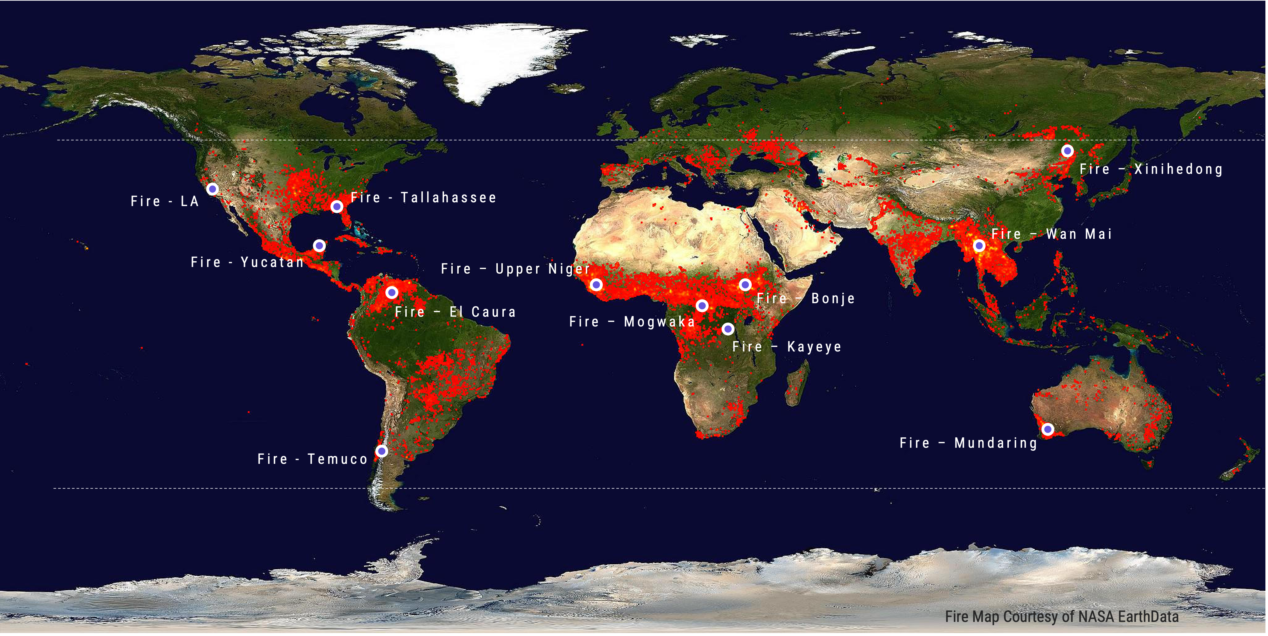
Thermal Imaging Targets
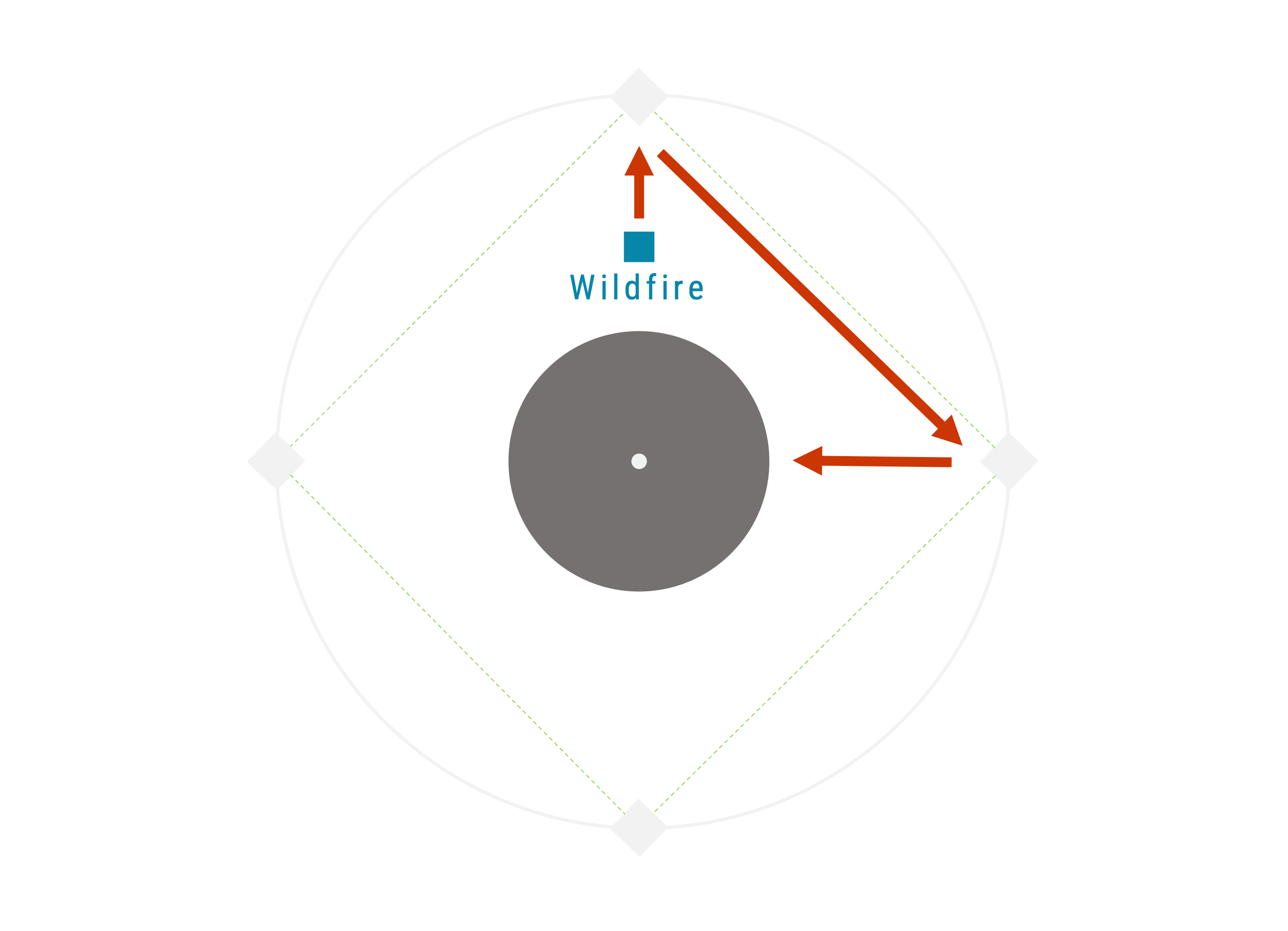
Laser Relay Constellation
Operational Modes#
- Uplink - Priority 4
- Antenna to Sedaro HQ Ground Station
- >10° satellite elevation angle condition
- Imaging - Priority 3
- Point Imager to Fire target
- Maximum 80° off-nadir pointing
- Crosslink - Priorty 2
- Point Antenna to relay satellite
- Line-of-sight to a relay satellite
- Idle Sunlight - Priority 1
- Maximum power/min drag pointing
- Sunlight condition
- Idle Eclipse - Priorty 0
- Minimum drag pointing
- Default mode
Design Capture: Follow the instructions below to build the Wildfire 3U CubeSat mission using Sedaro Satellite#
Step 1: Create and name your first mission. This mission version can be cloned or deleted.
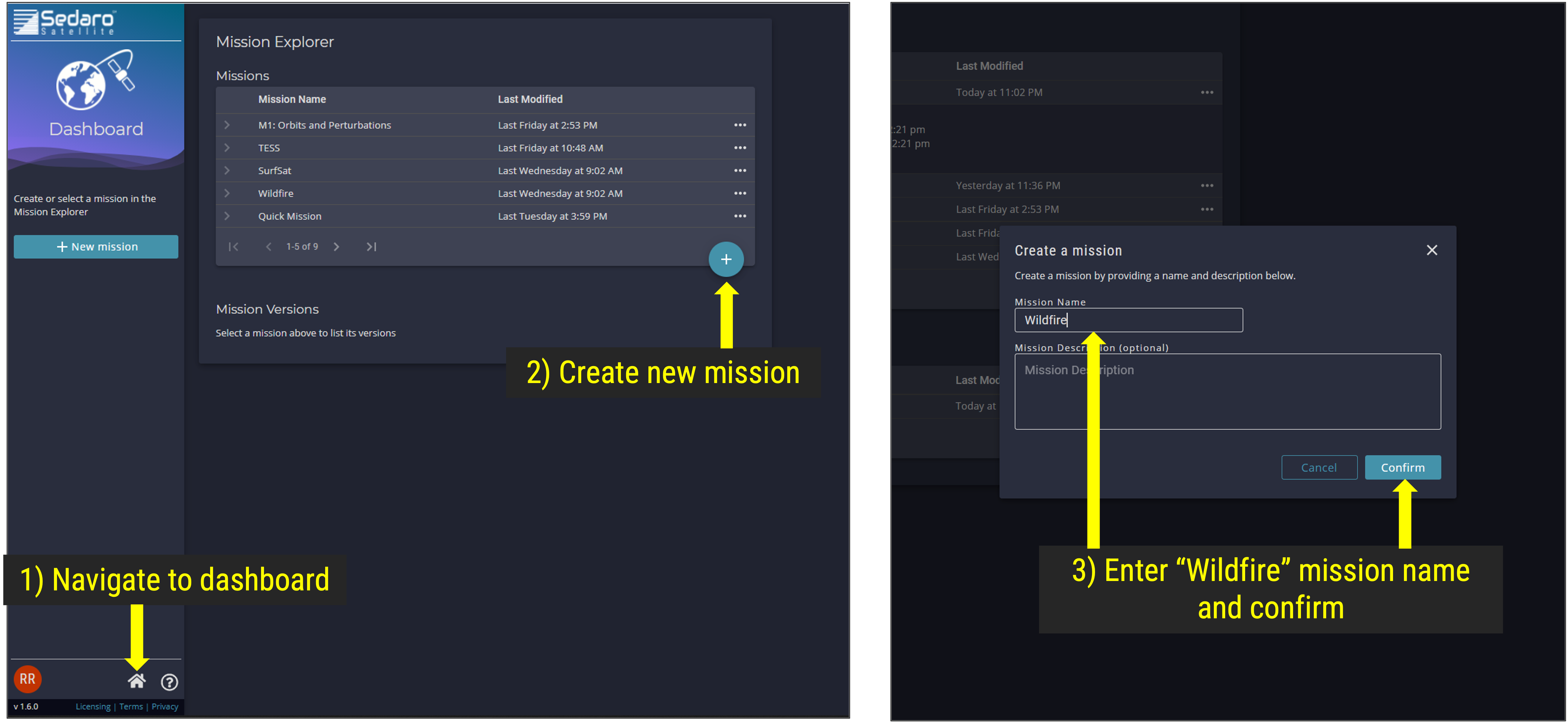
Mission Explorer - Create a New Mission
Step 2: Create and name your first mission version. This mission version can be cloned or deleted. After saving the new mission version name, open the Mission Designer Module shown in the navigation panel.
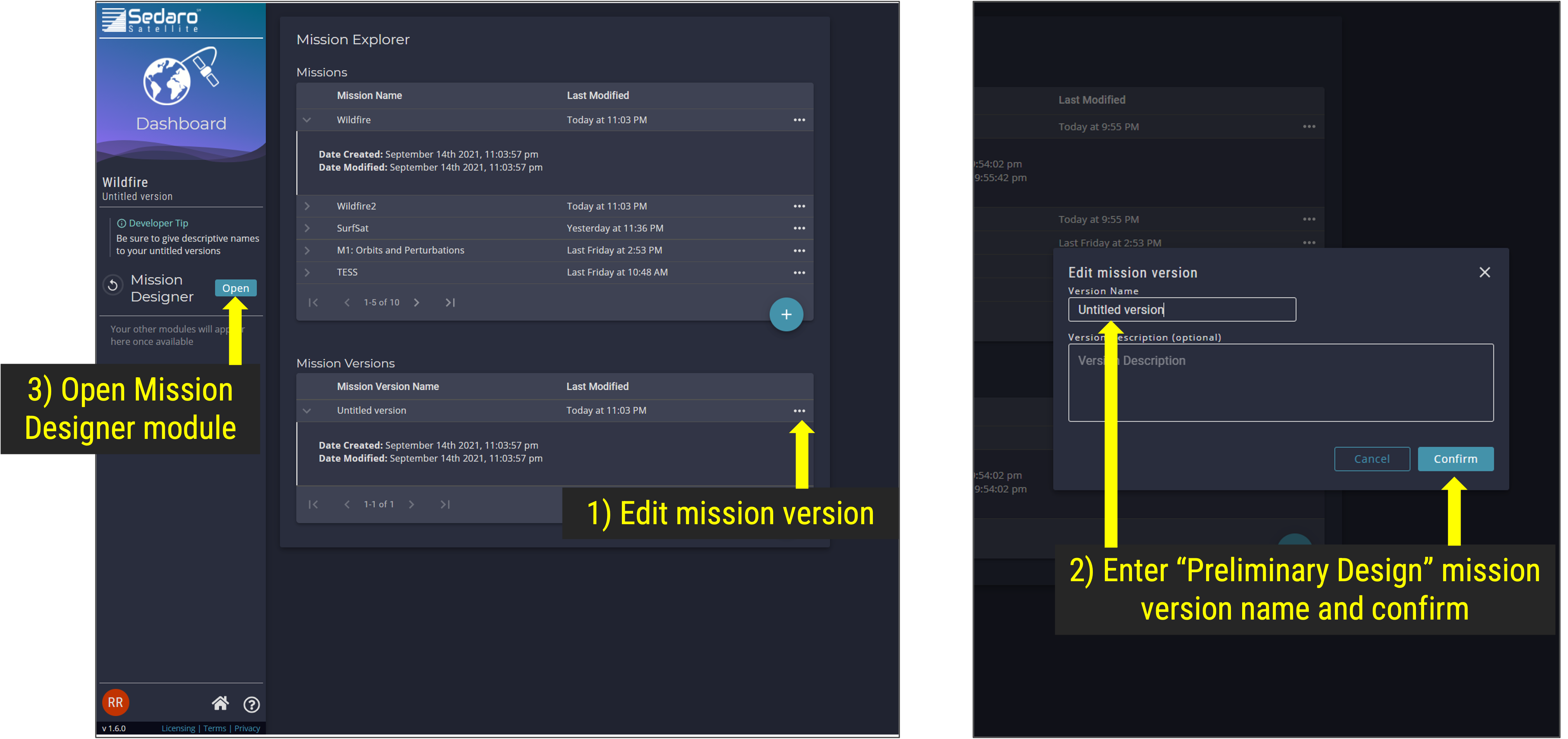
Mission Explorer - Create a New Mission Version
Step 3: Under the Orbit & Time Segment input orbit and time parameters
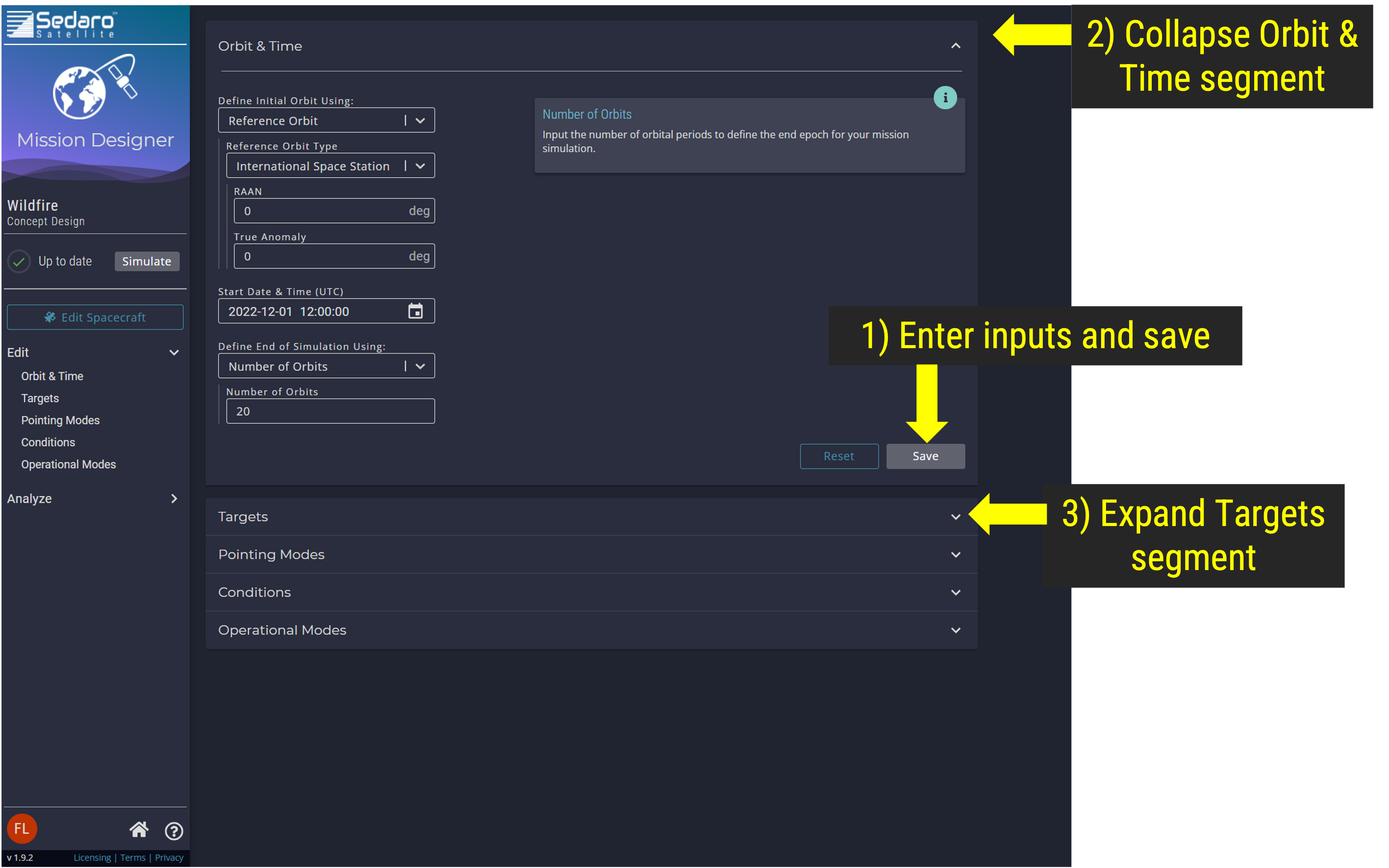
Orbit and Time Segment
Step 4: Under the Targets Segment select the "plus" sign to add Targets
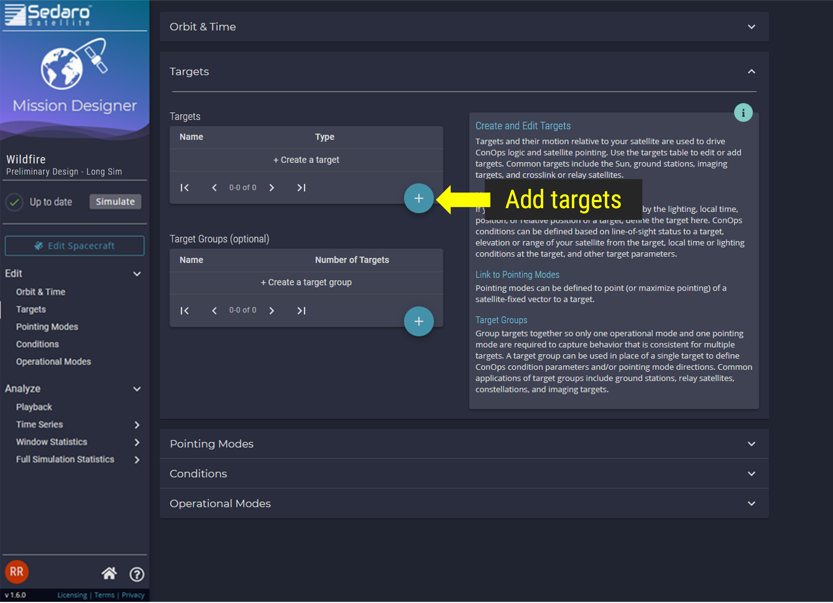
Targets Segment
Step 4.1: Uplink ground station target at Sedaro HQ
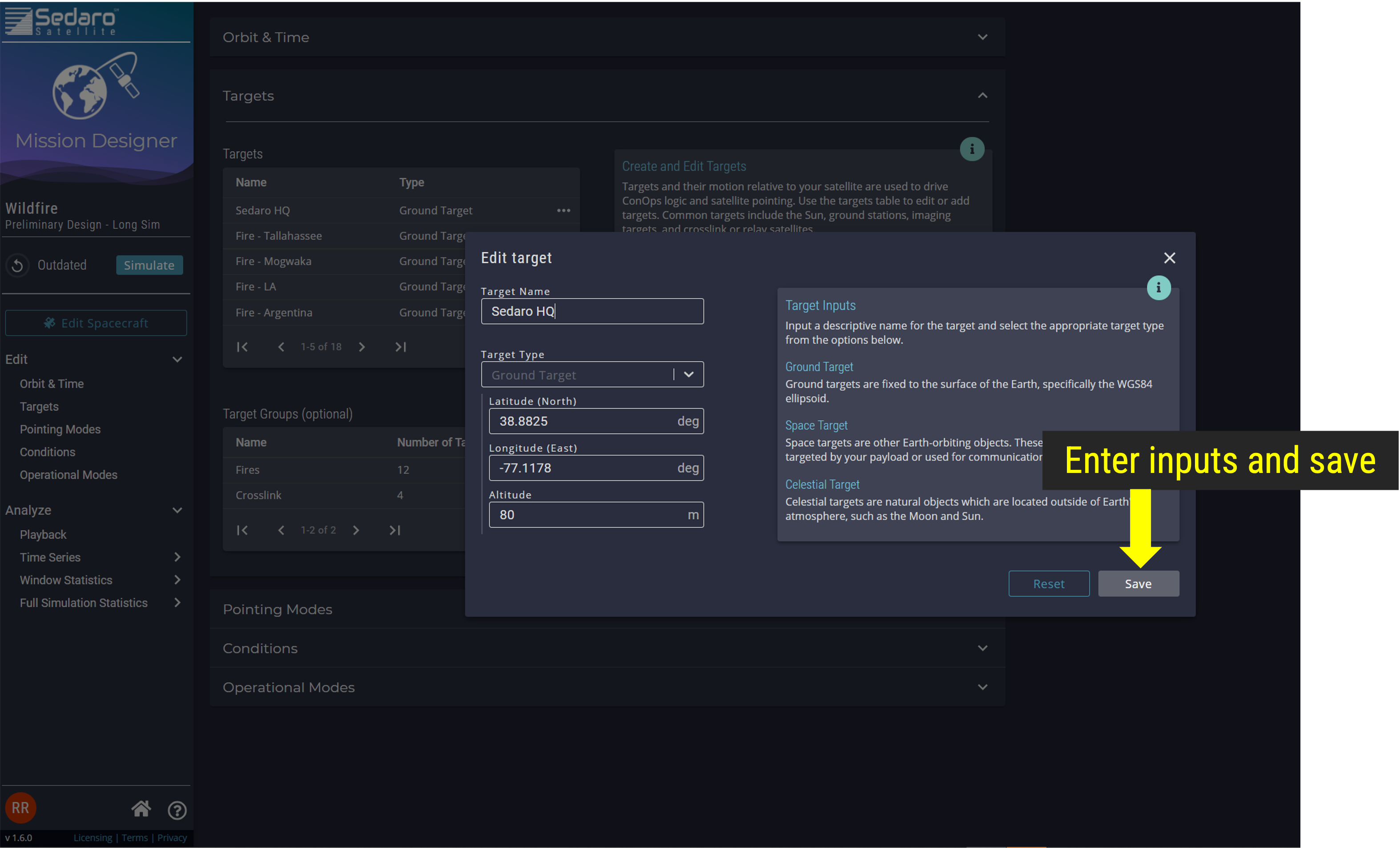
Sedaro HQ Coordinates
Step 4.2: Laser Comm Relay Satellite Targets (4 Space Targets)
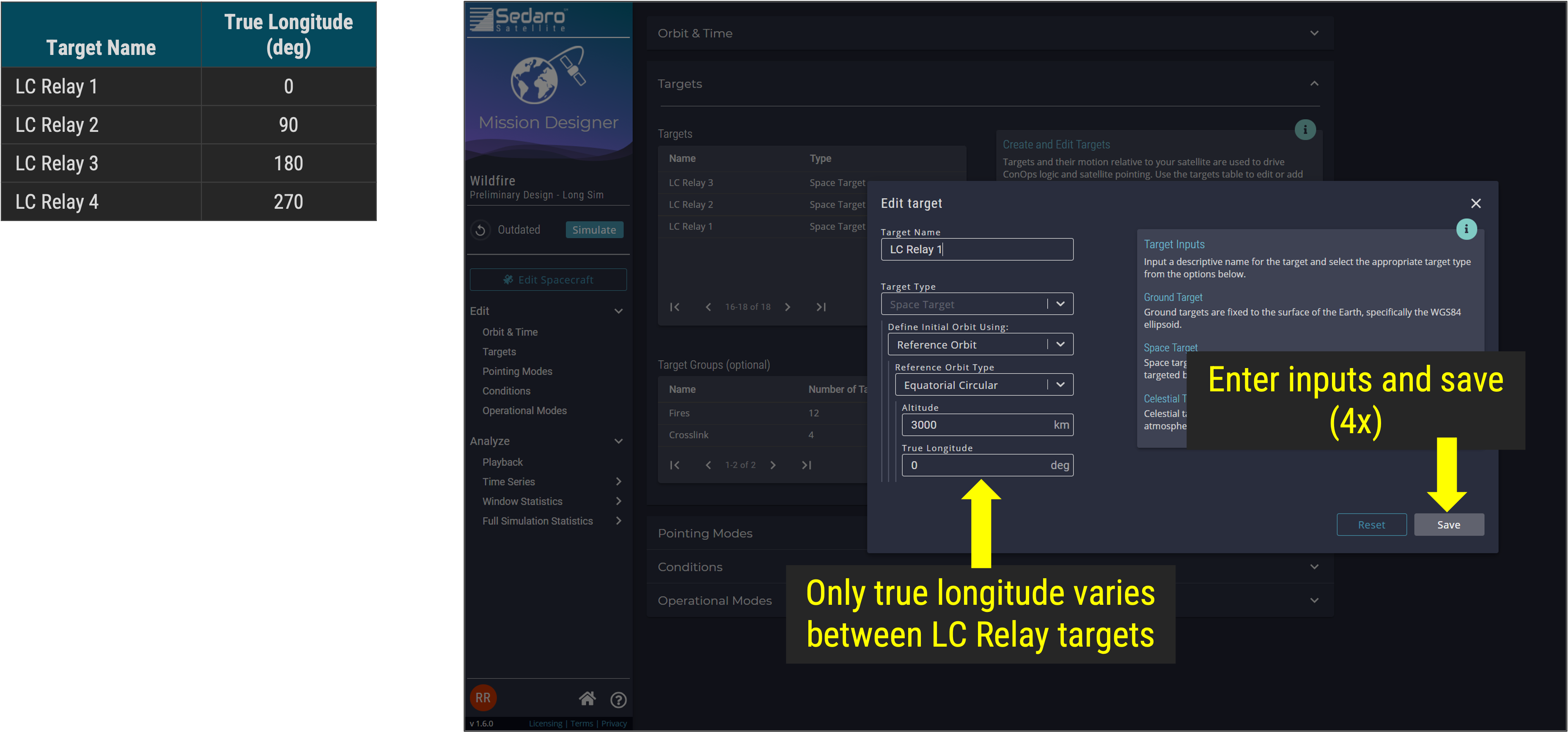
LC Relay Targets
Step 4.3: Add active wildfire imaging targets (12 Ground Targets)
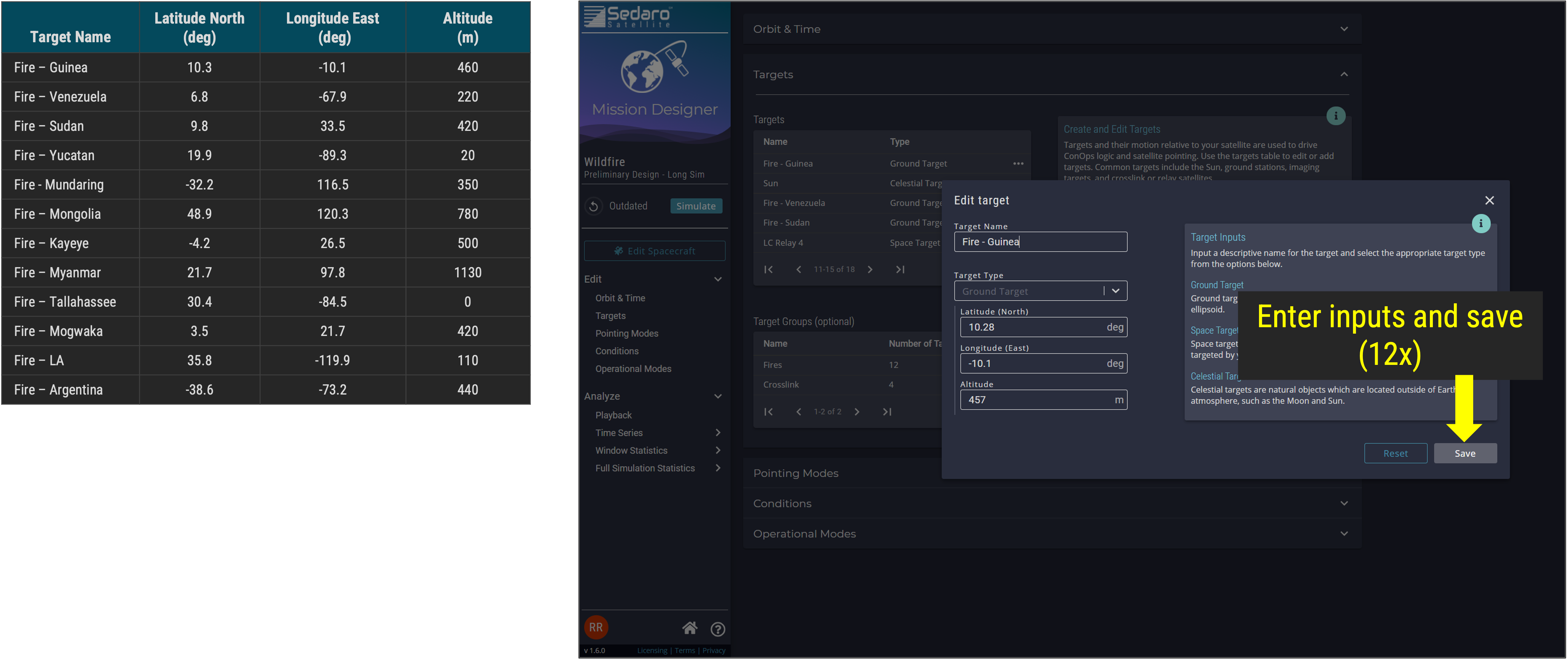
Wildfire Location Targets
Step 4.4: Add the Sun as a Celestial target
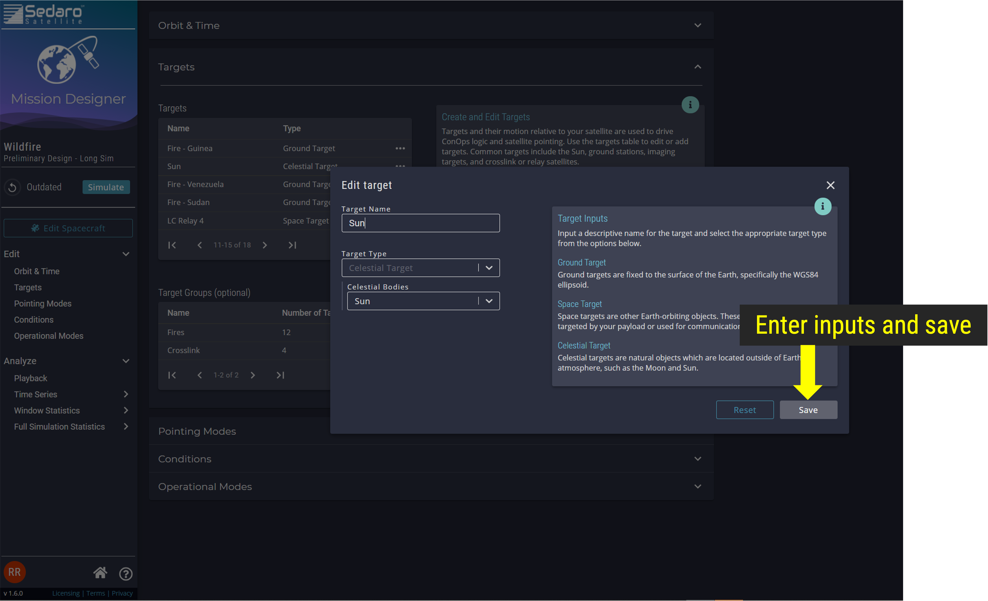
Sun Target
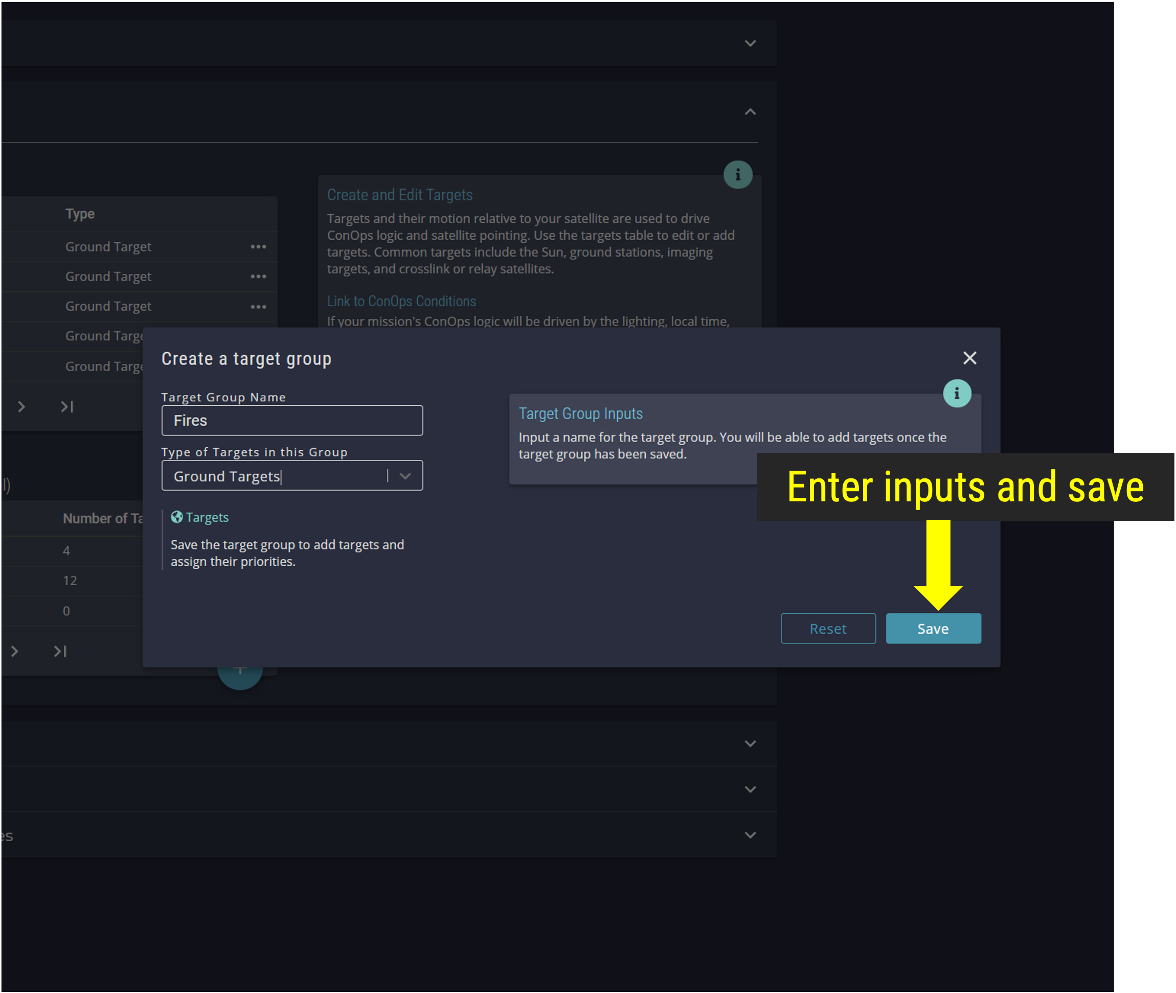
Step 4.5: Add a target group
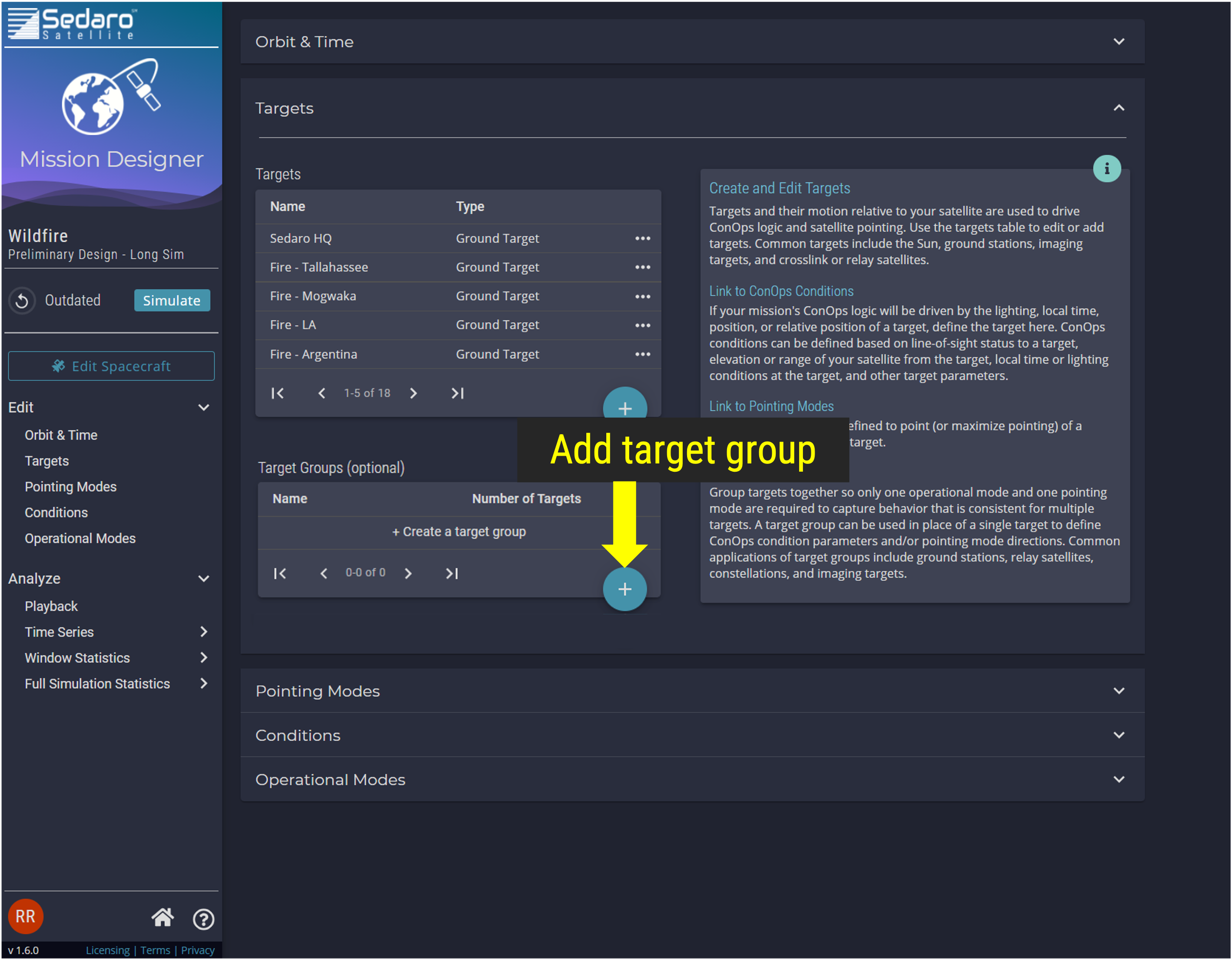
Target Group
Step 4.6: Add relay constellation target group
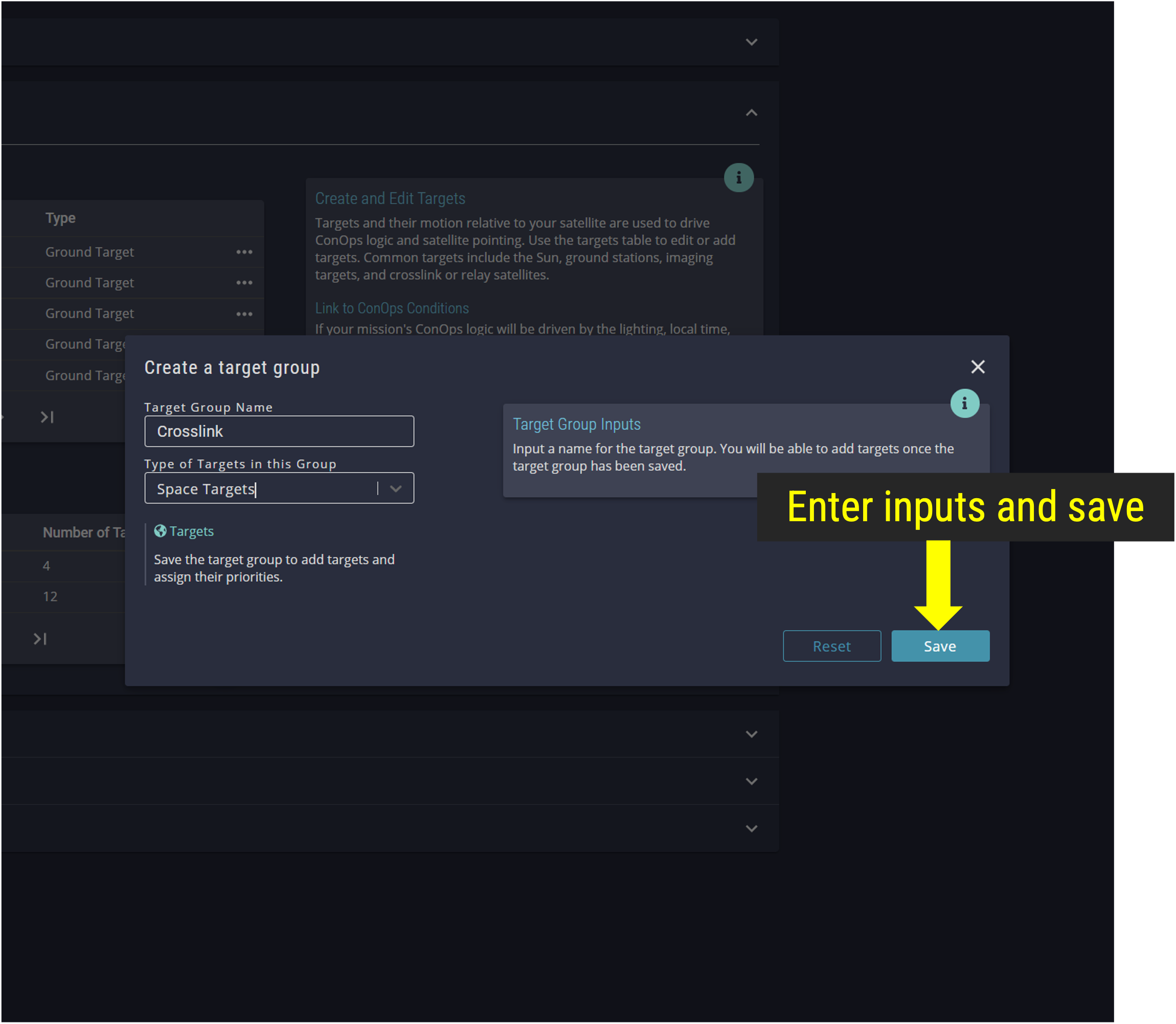
Relay Constellation Target Group
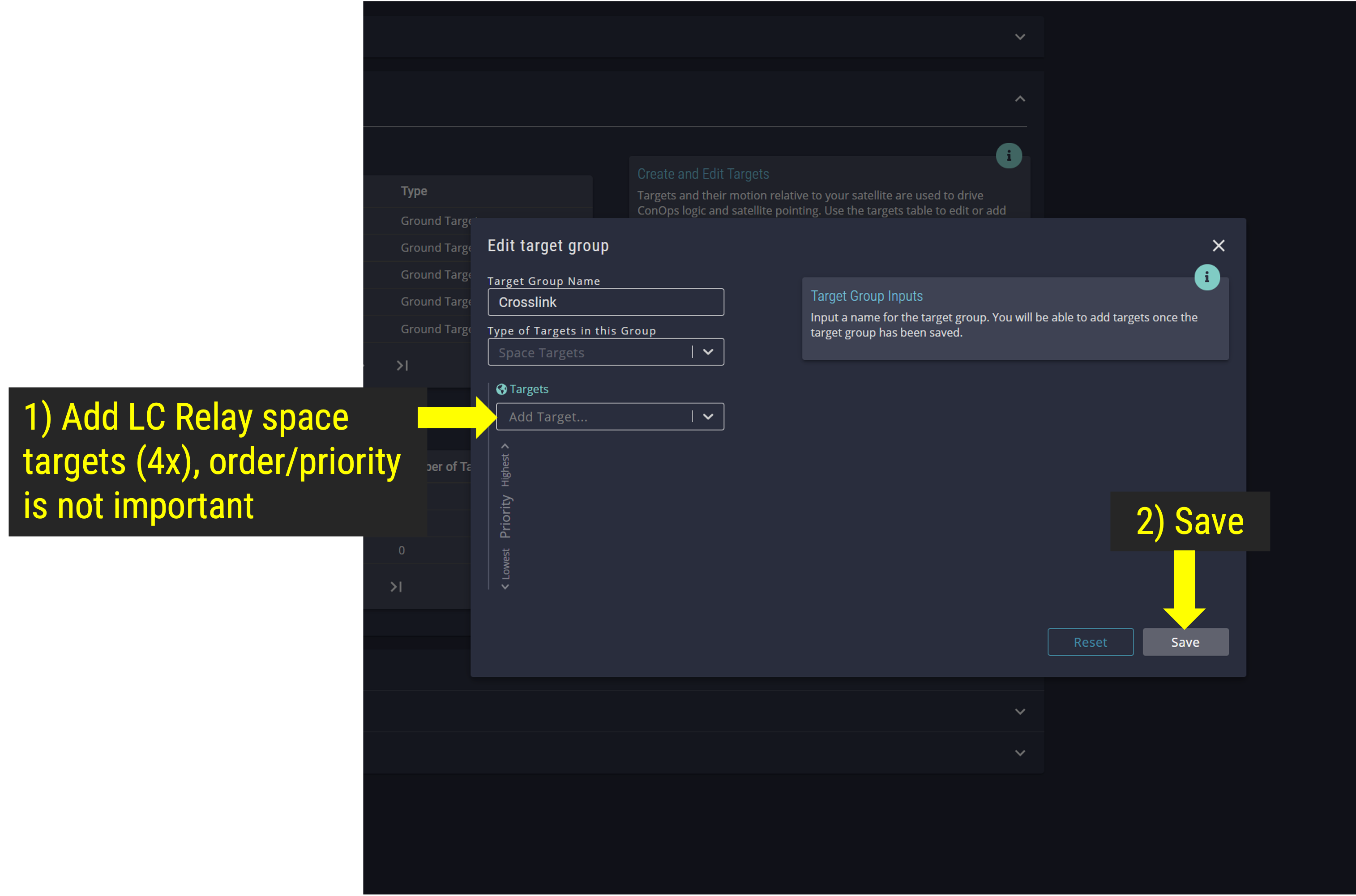
Save Relay Constellation Target Group
Step 4.7: Add active wildfire imaging target group
Active Wildefire Imaging Target Group
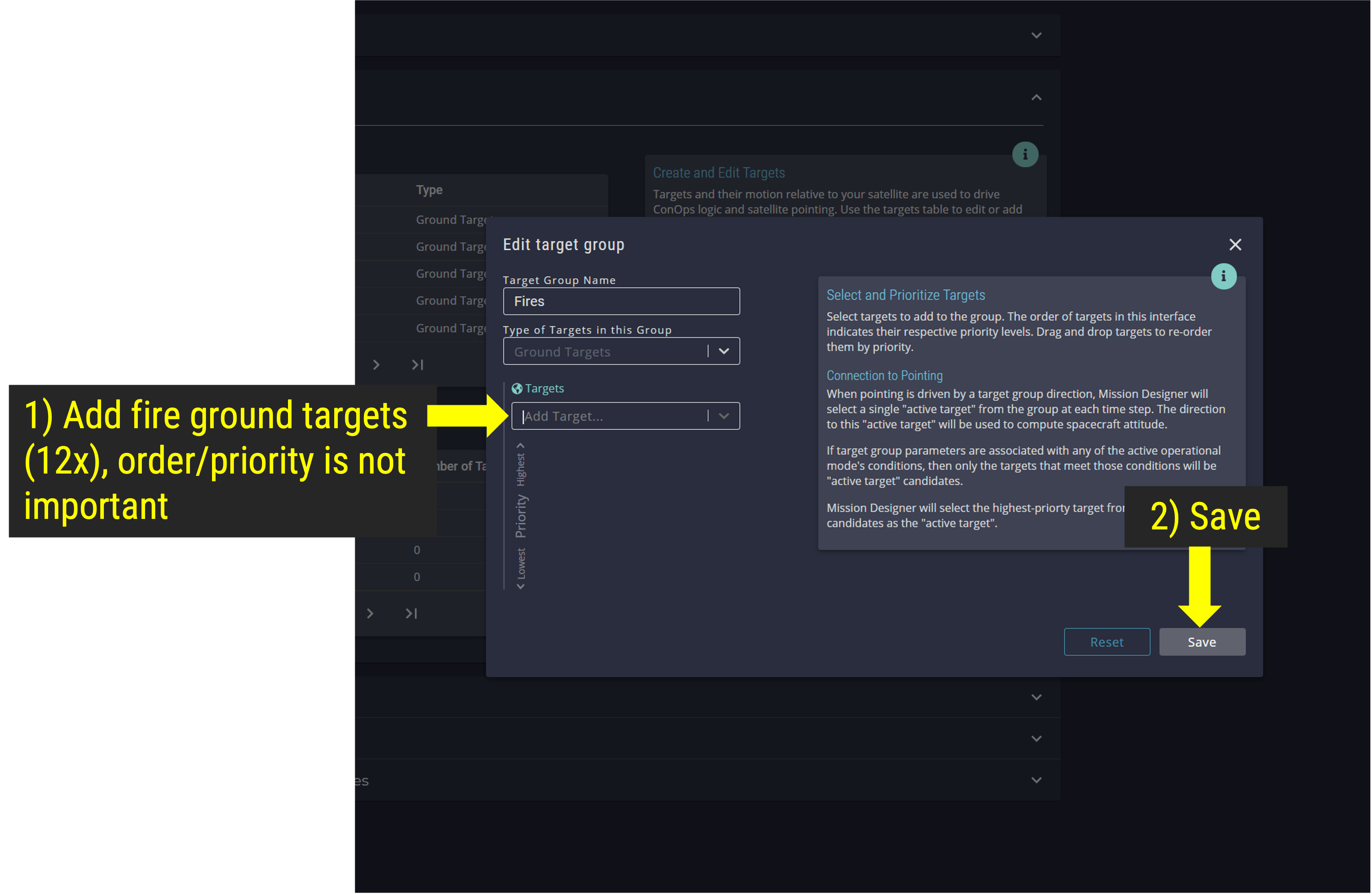
Active Wildefire Imaging Target Group
Step 5: Open the Spacecraft Dialog
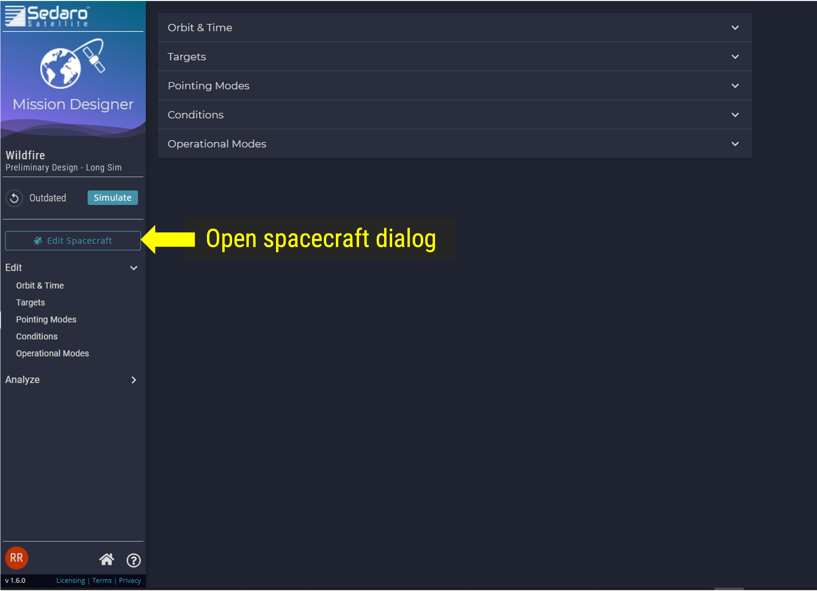
Spacecraft Dialog
Step 5.1: Add a custom CAD Model or use a preset model
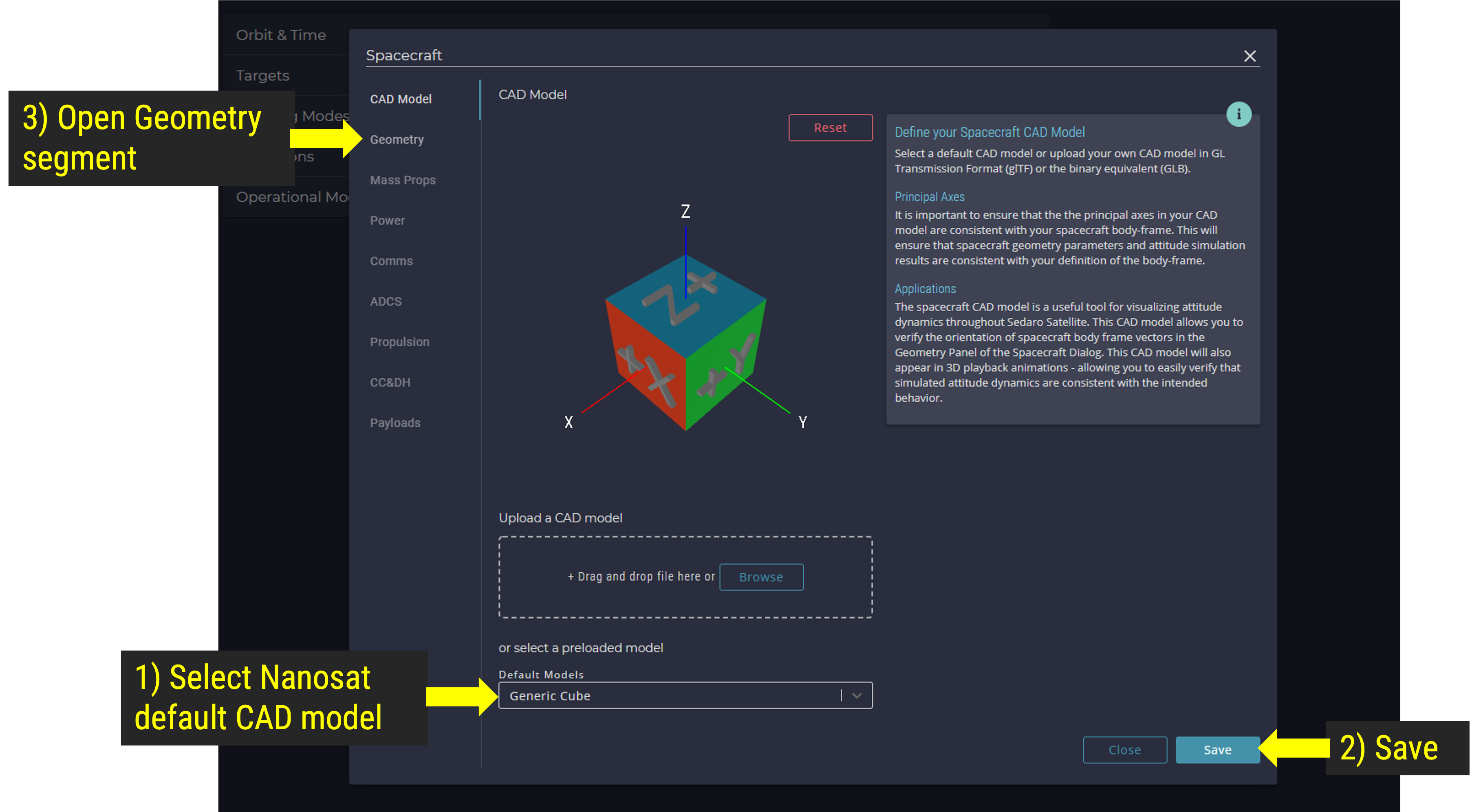
Add custom CAD model
Step 5.2: Add/Save Imager Body Frame Vector
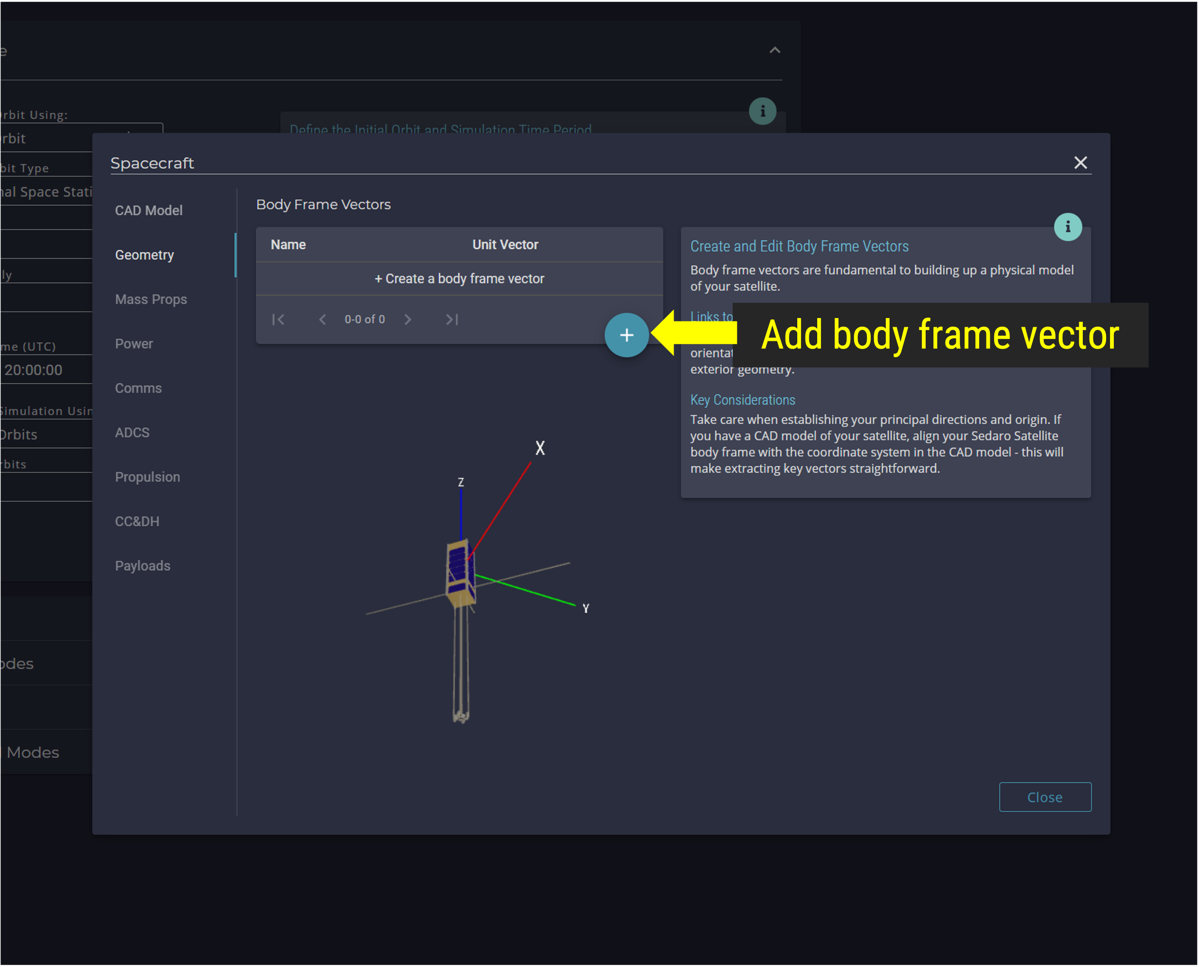
Add Imager Body Frame Vector
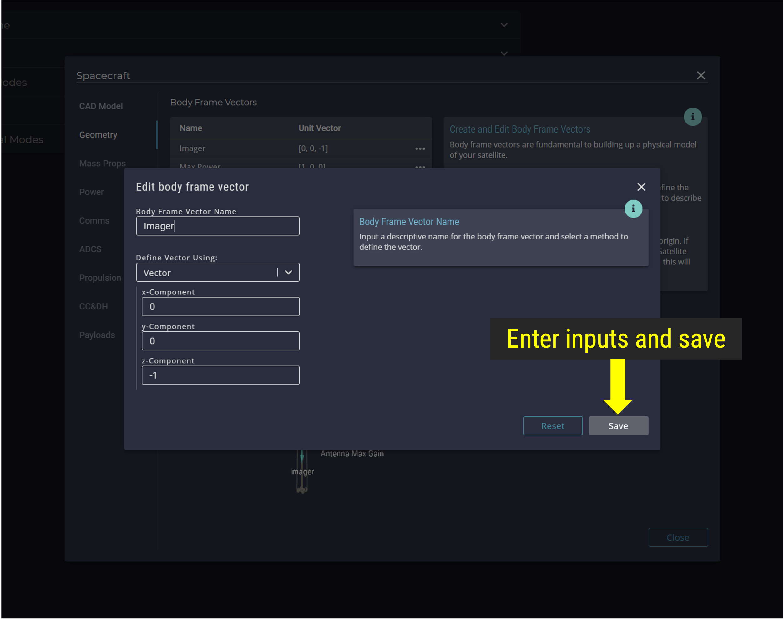
Save Imager Body Frame Vector
Step 5.3: Add/Save Max Power Body Frame Vector
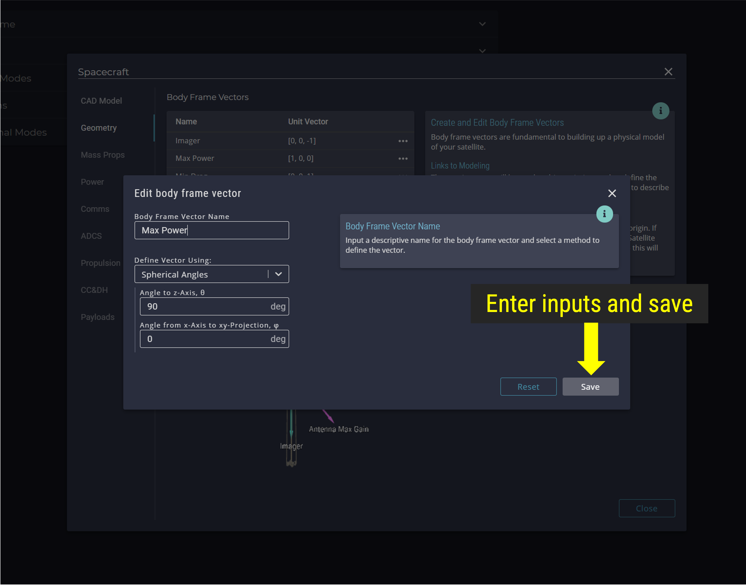
Max Power Body Frame Vector
Step 5.4: Add/Save Min Drag Body Frame Vector
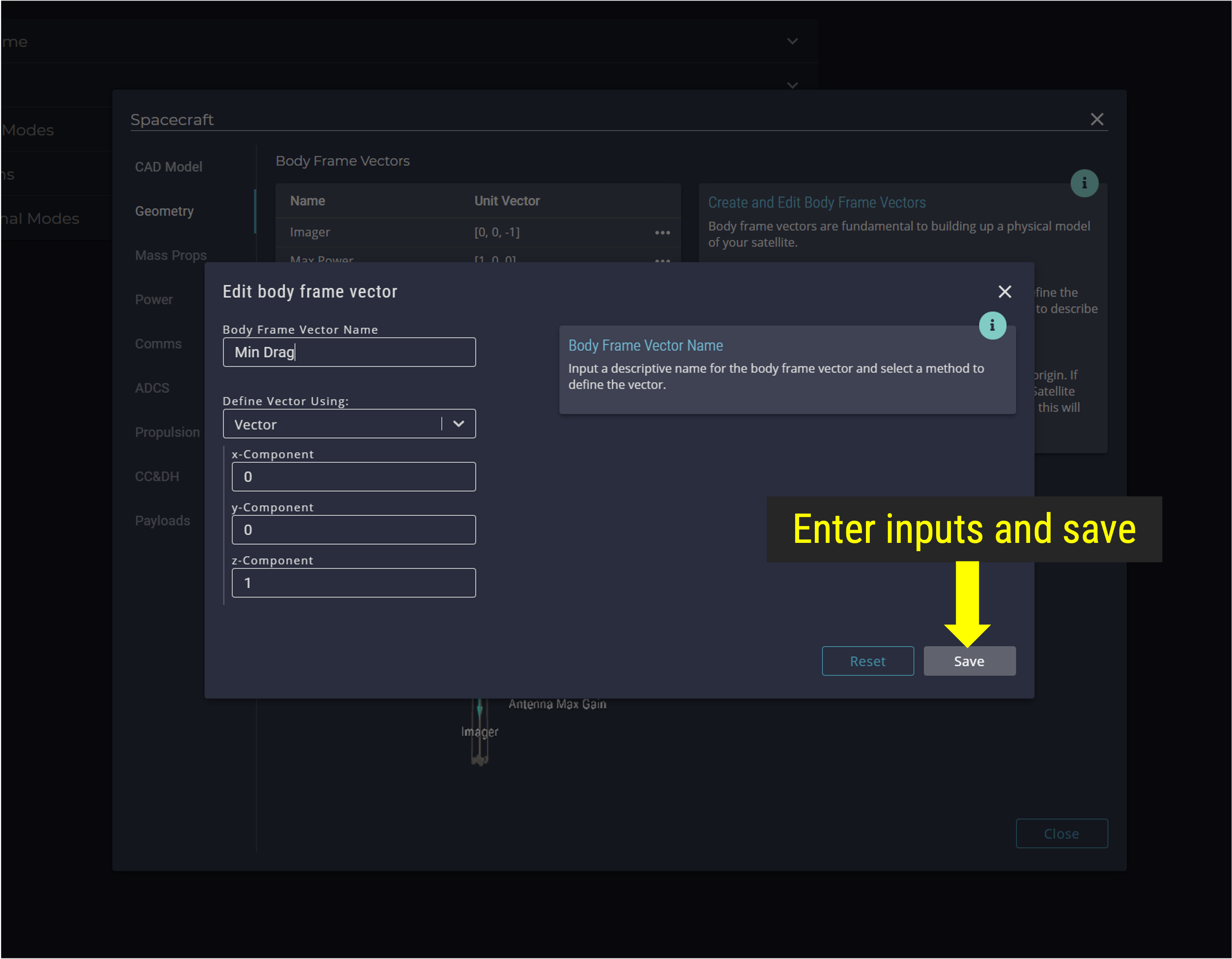
Min Drag Body Frame Vector
Step 5.5: Add/Save Antenna Max Gain Body Frame Vector
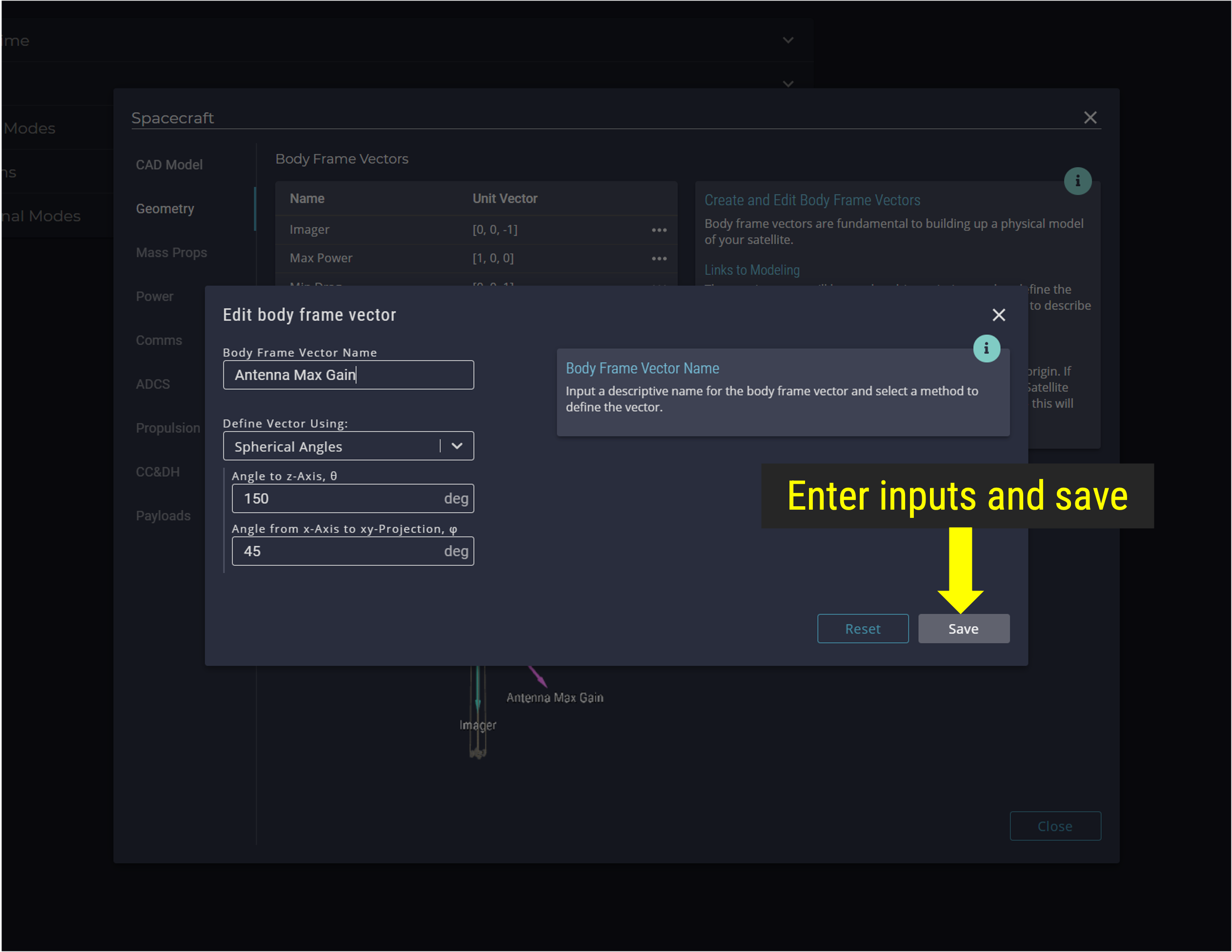
Antenna Body Frame Vector
Step 5.6: Verify and Save Body Frame Vectors
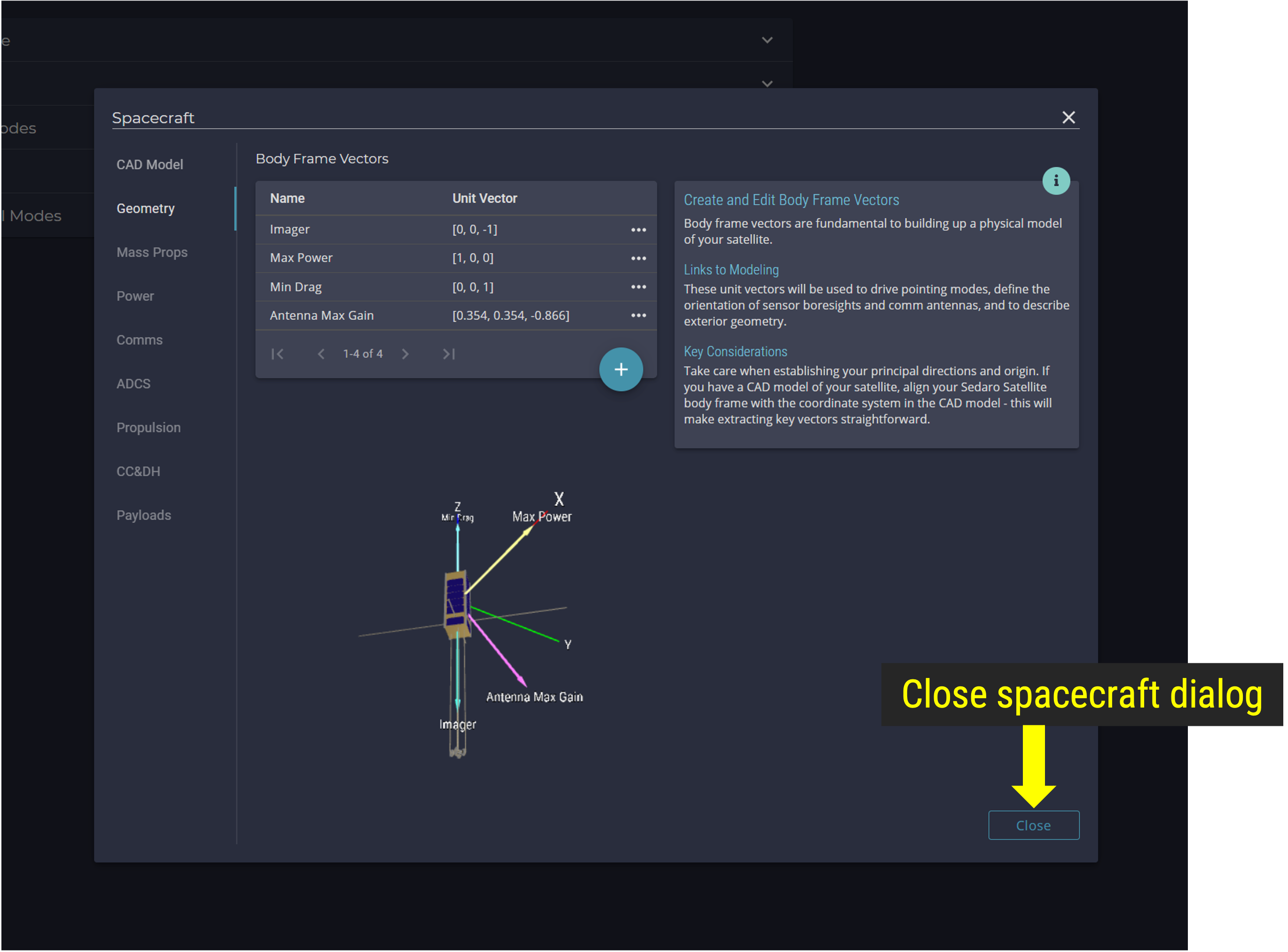
Save Body Frame Vectors
Step 6: Add Pointing Modes
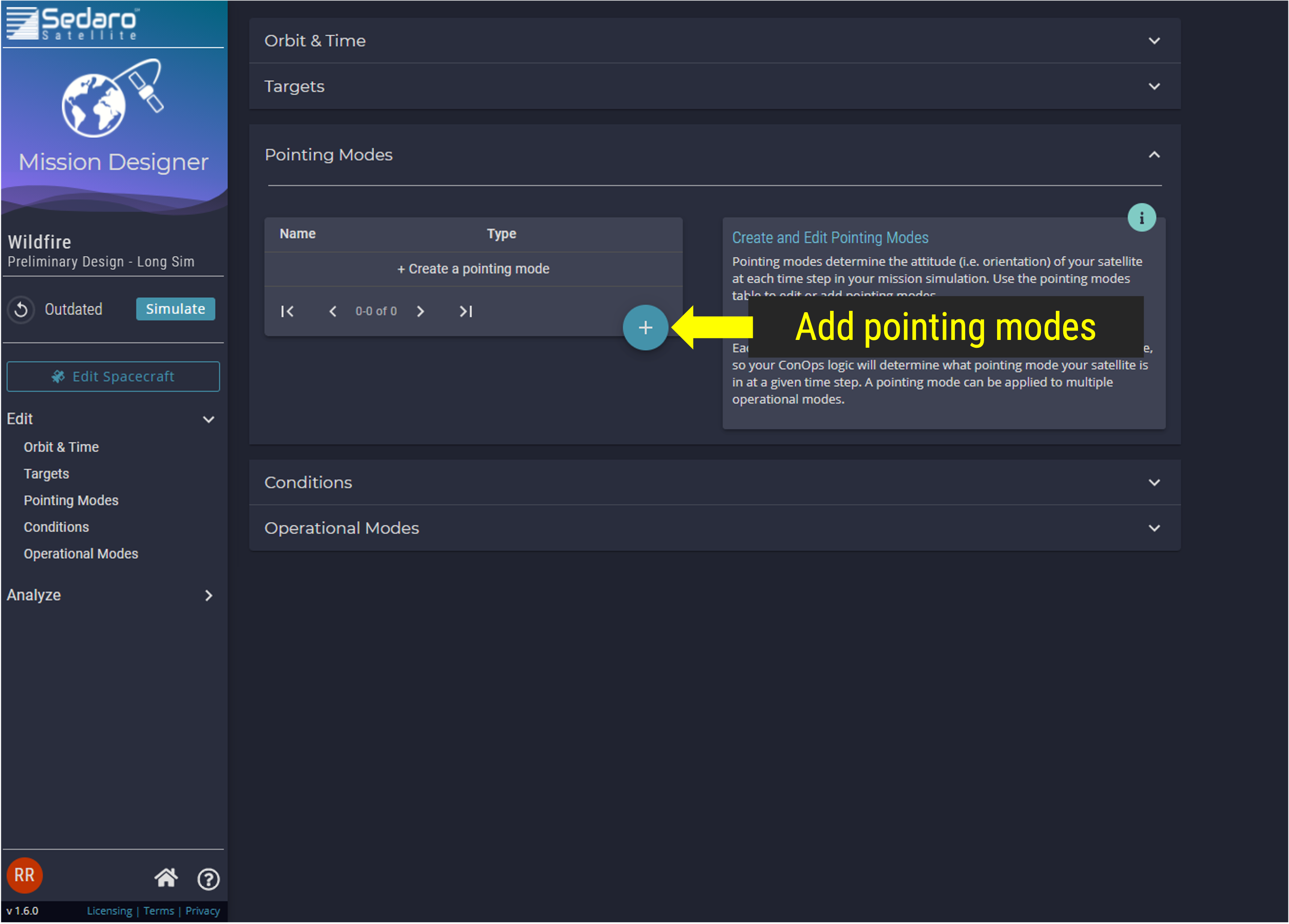
Add Pointing Modes
Step 6.1: Add Crosslink Pointing Mode
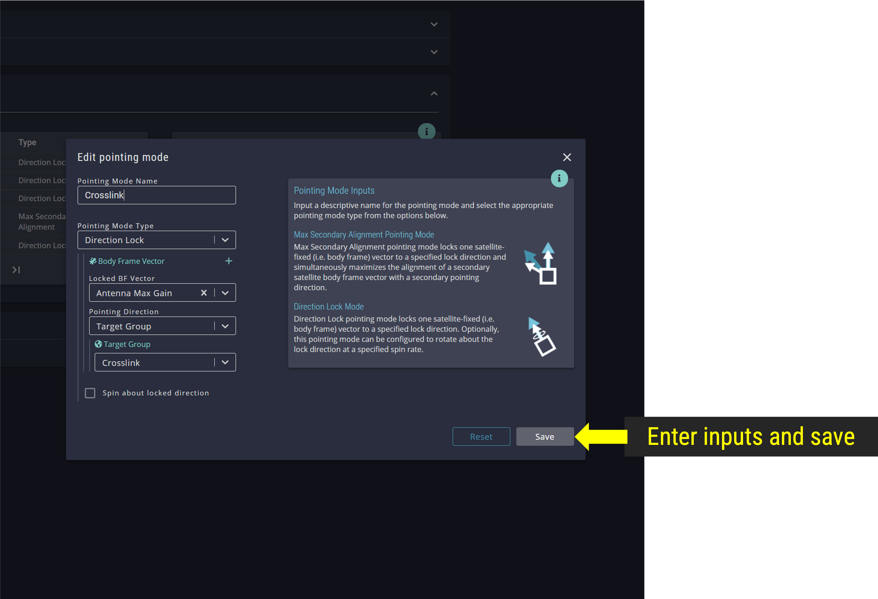
Add Crosslink Pointing Mode
Step 6.2: Add Uplink Pointing Mode
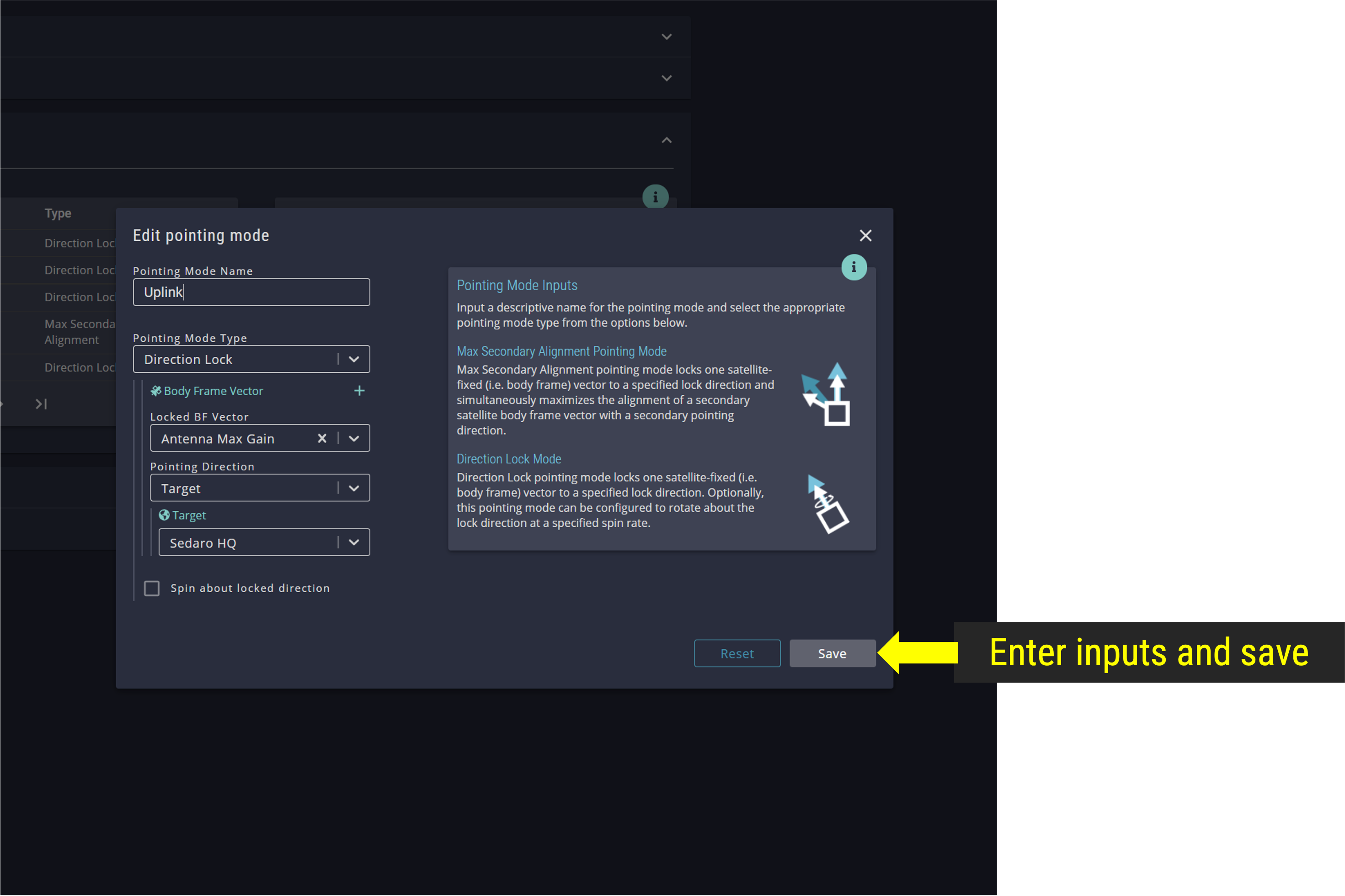
Add Uplink Pointing Mode
Step 6.3: Add Min Drag Link Pointing Mode
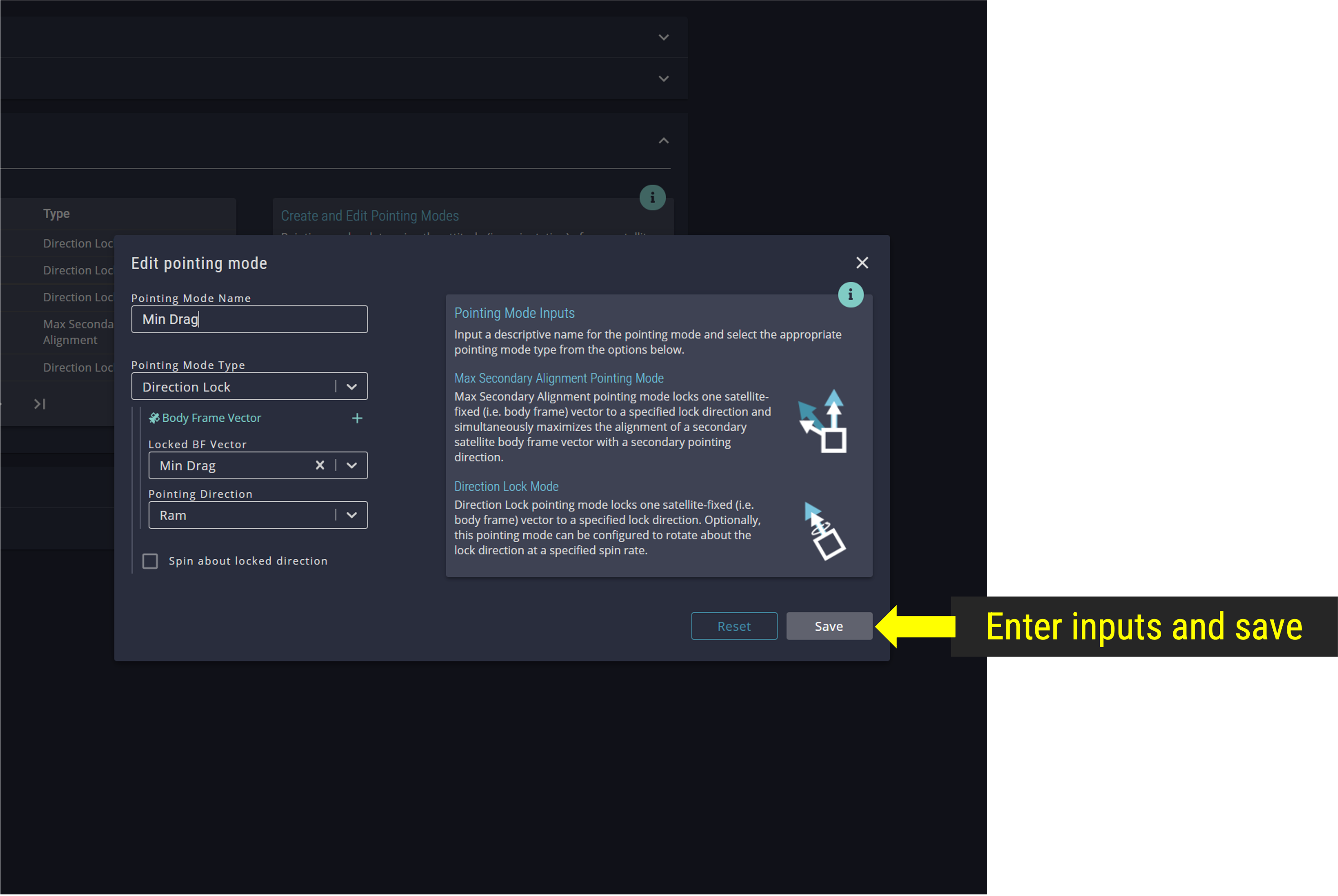
Add Min Drag Link Pointing Mode
Step 6.4: Add Max Power Pointing Mode
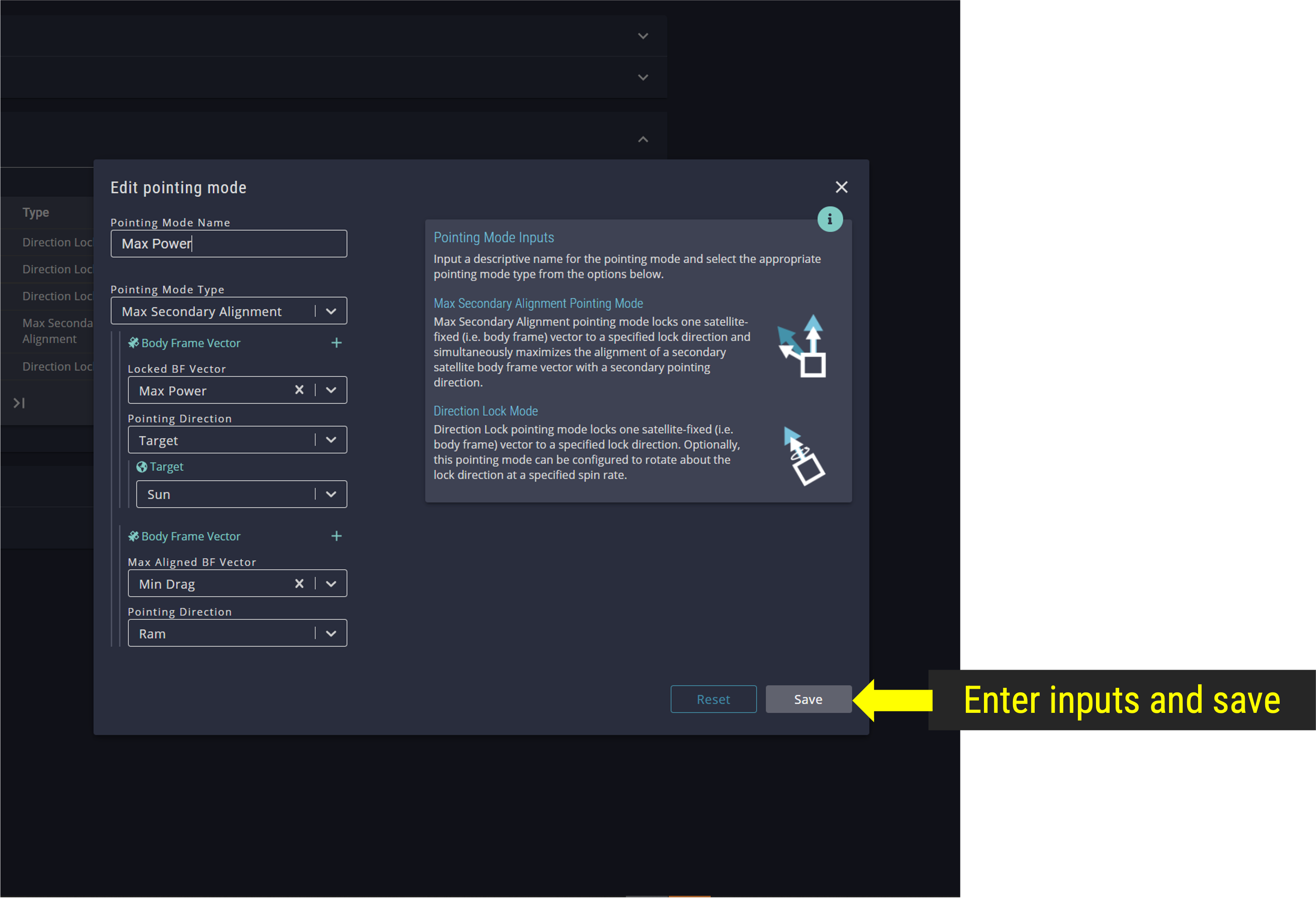
Add Max Power Pointing Mode
Step 6.5: Add Imaging Pointing Mode
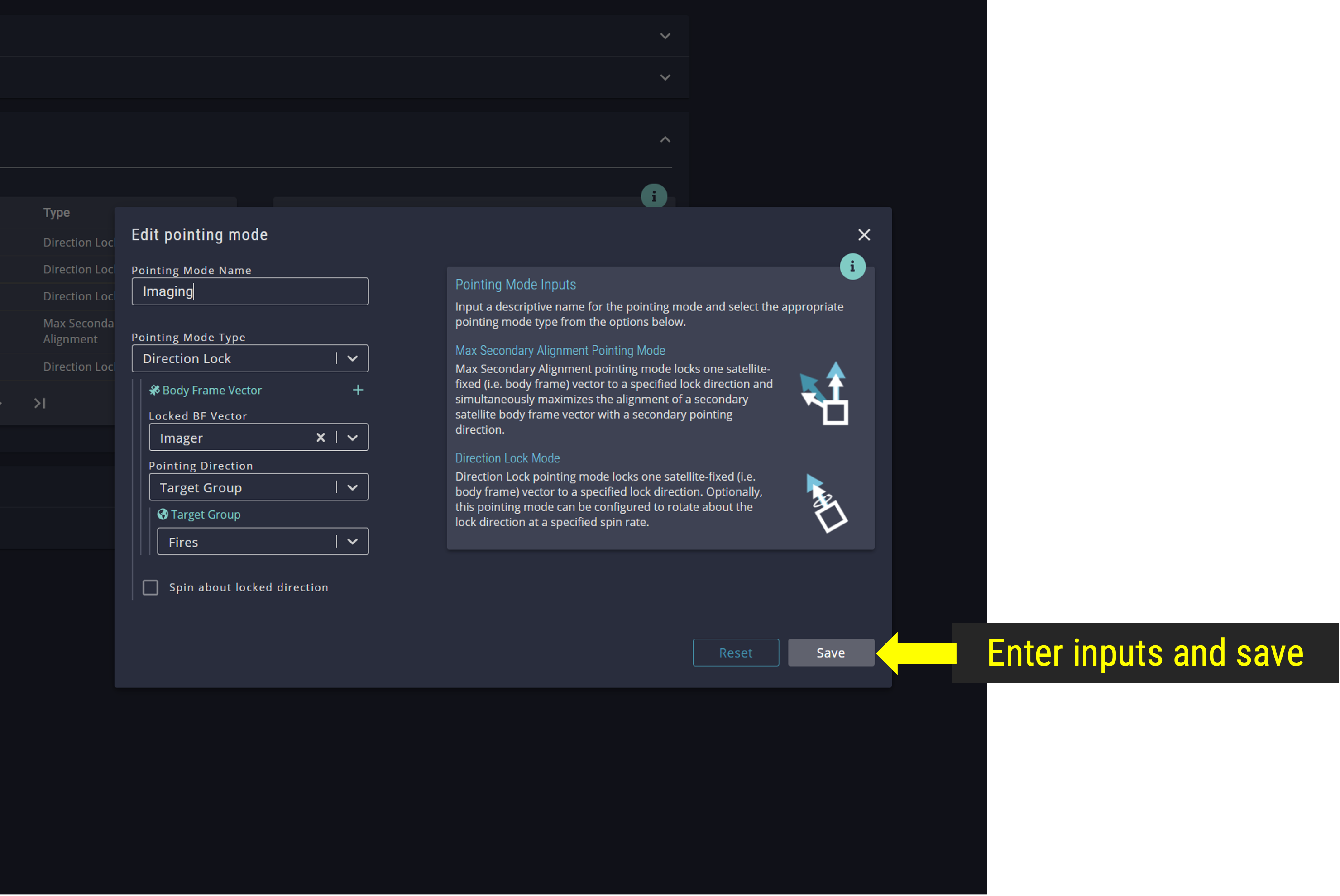
Add Imaging Pointing Mode
Step 7: Add Conditions
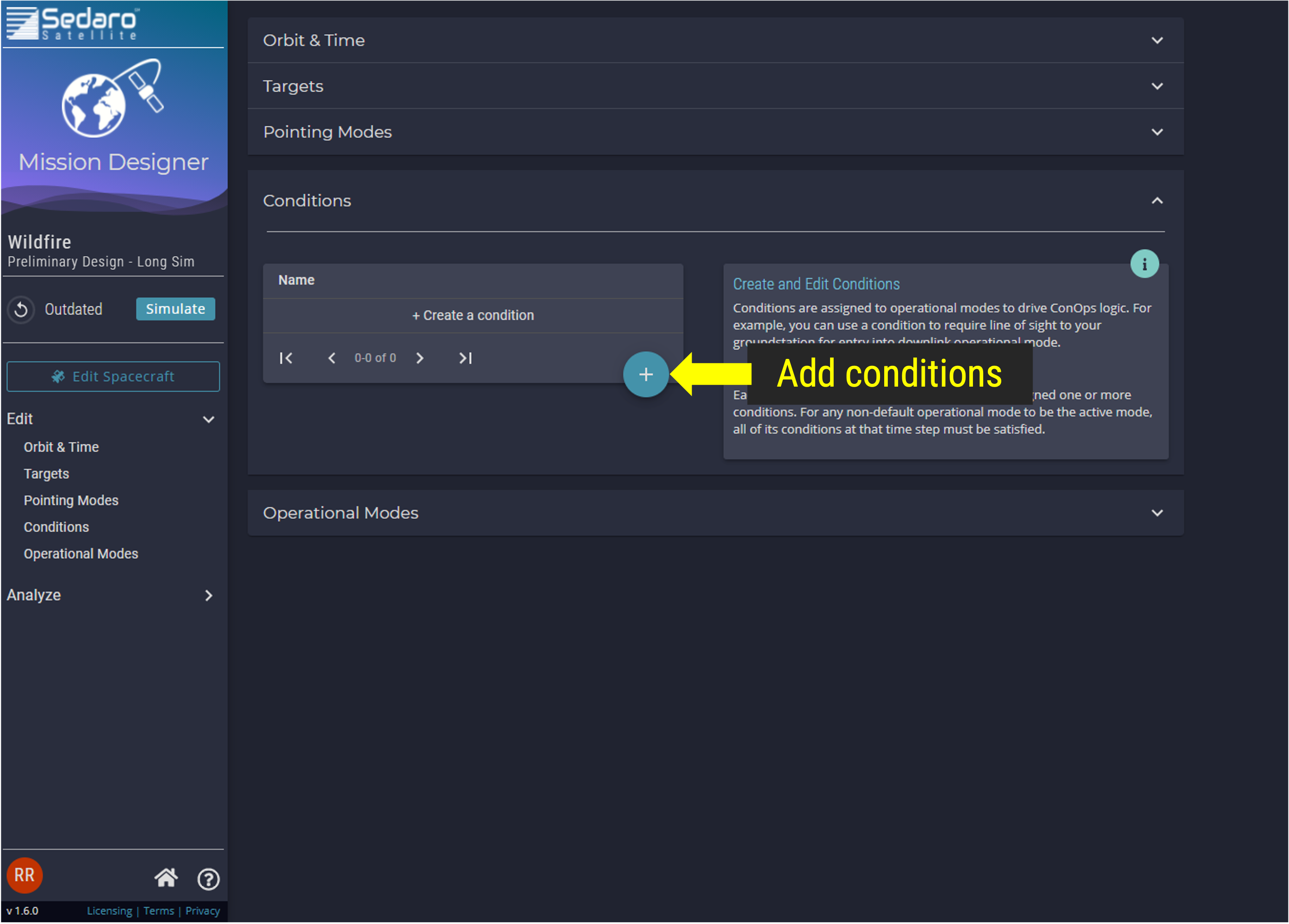
Add Conditions
Step 7.1: Condition for Maximum Off-Nadir Imaging angle
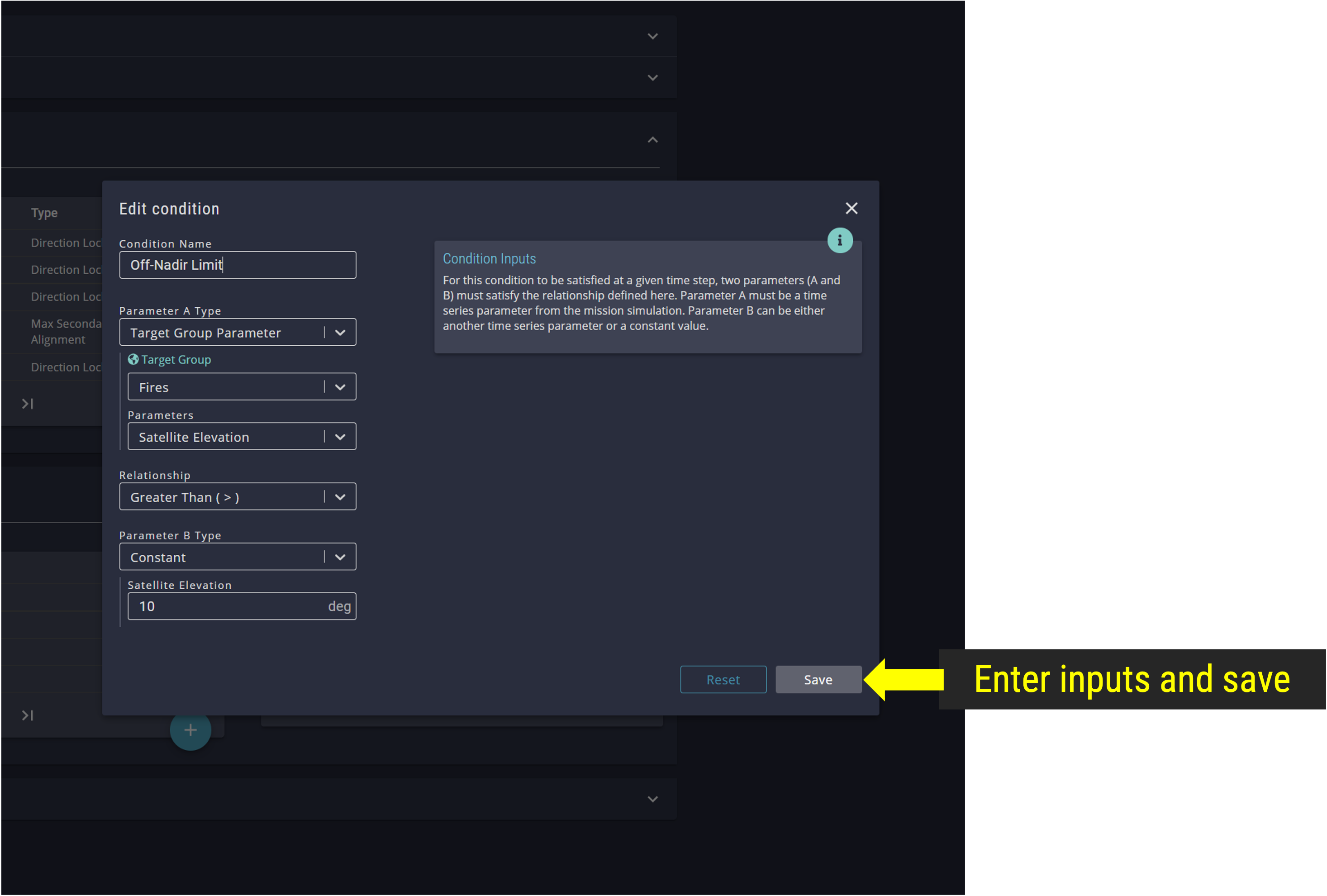
Add Max Off-Nadir Condition
Step 7.2: Condition for Line of Sight to a Crosslink Satellite
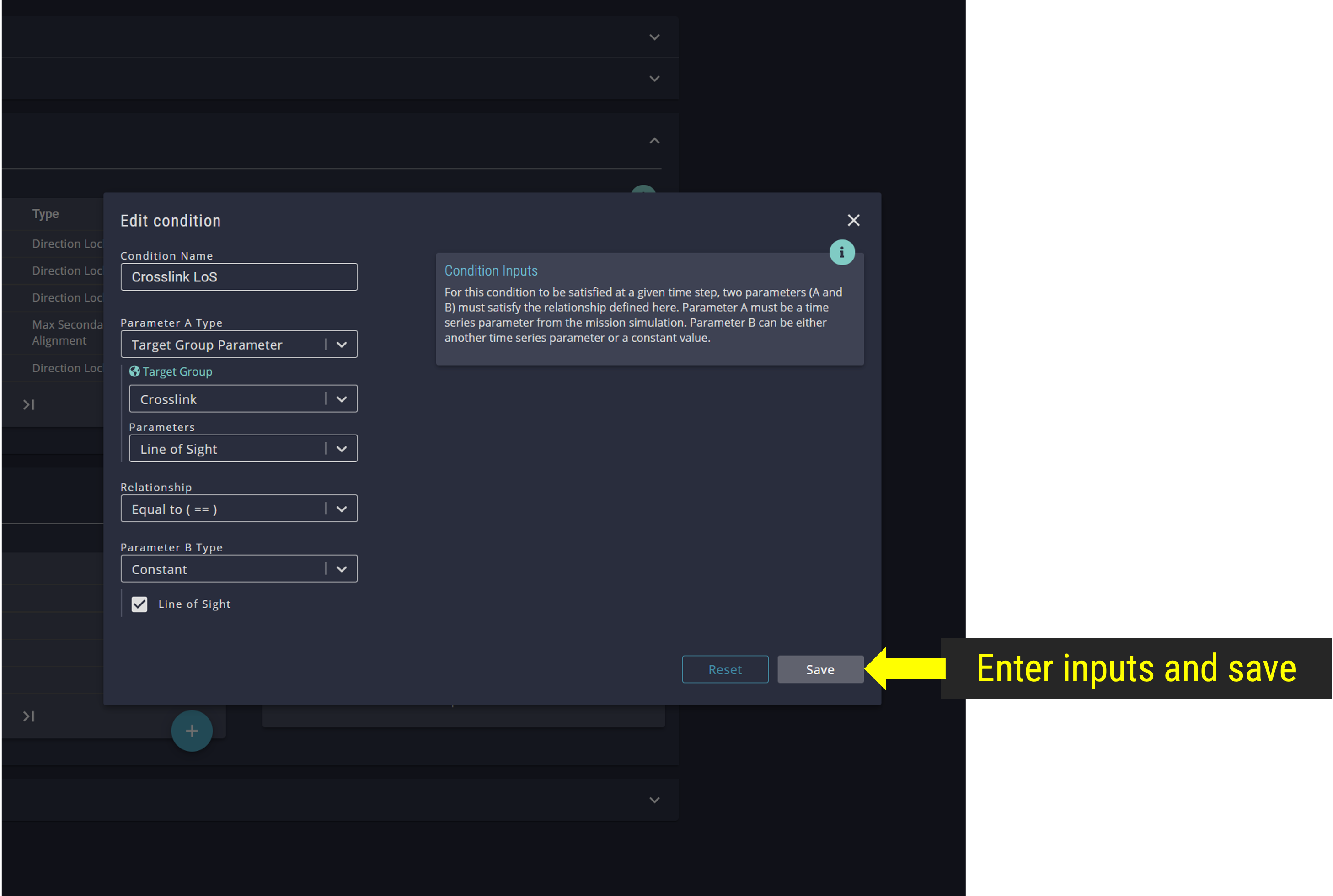
Add Line of Sight to a Crosslink Satellite Condition
Step 7.3: Condition for Eclipse State
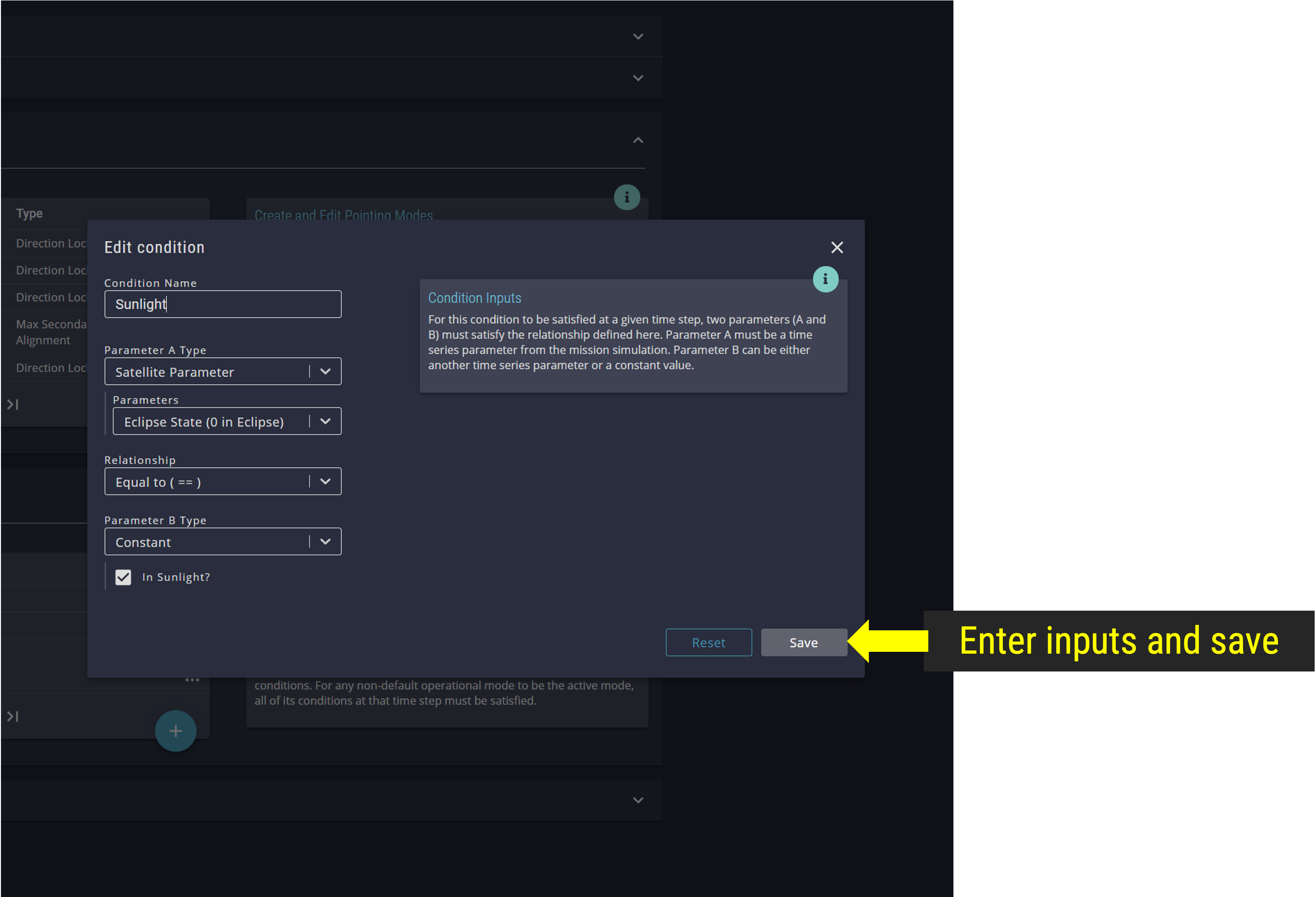
Add Eclipse State Condition
Step 7.4: Condition for Satellite Elevation from Ground Station
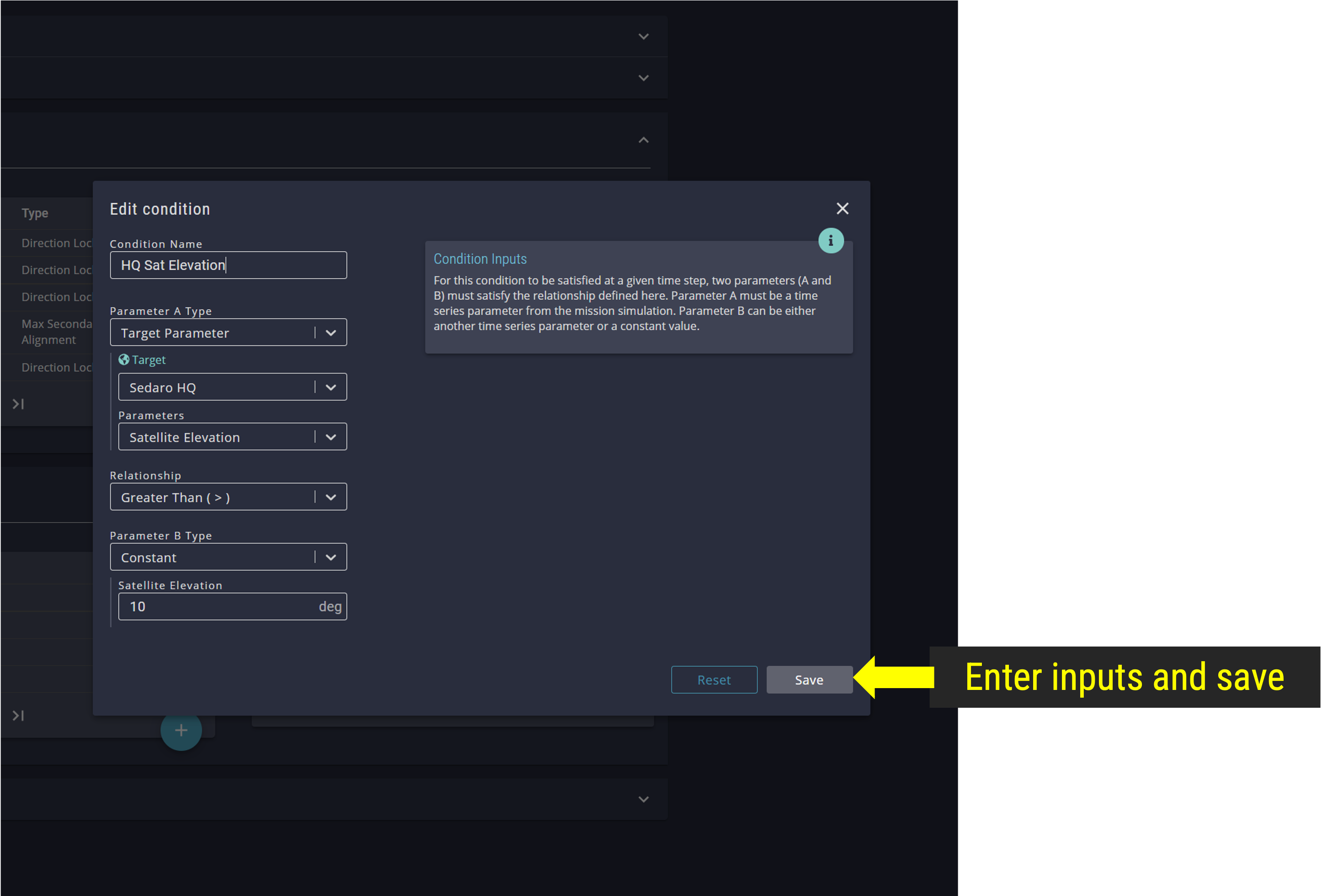
Add Satellite Elevation from Ground Station Condition
Step 8: Add Operational Modes
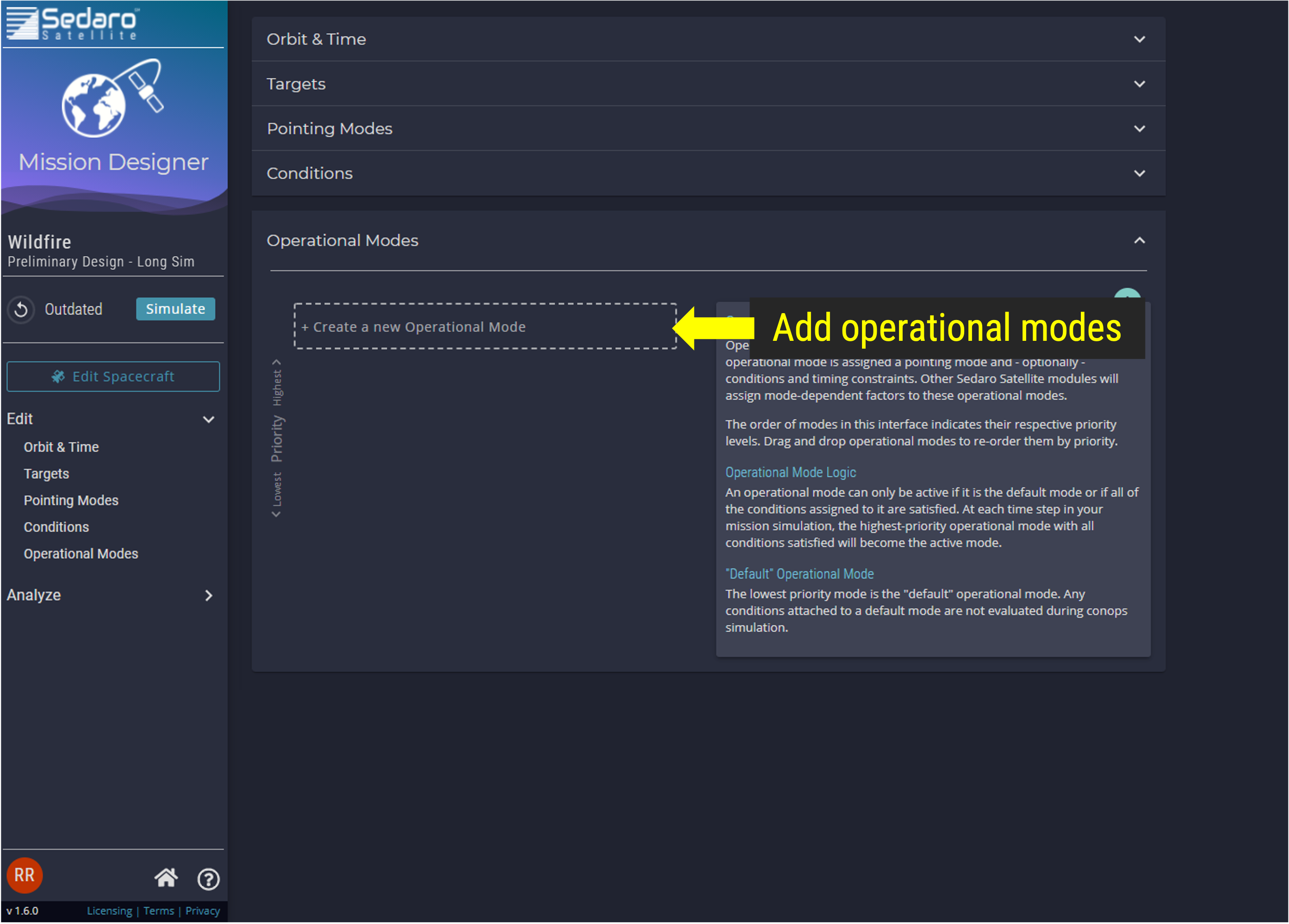
Op Modes
Step 8.1: Add Uplink Operational Mode
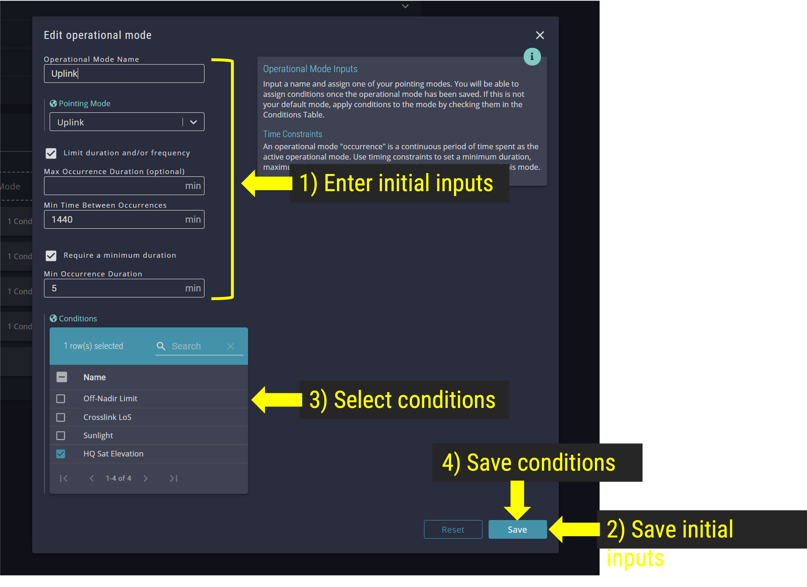
Uplink Op Mode
Step 8.2: Add Imaging Operational Mode
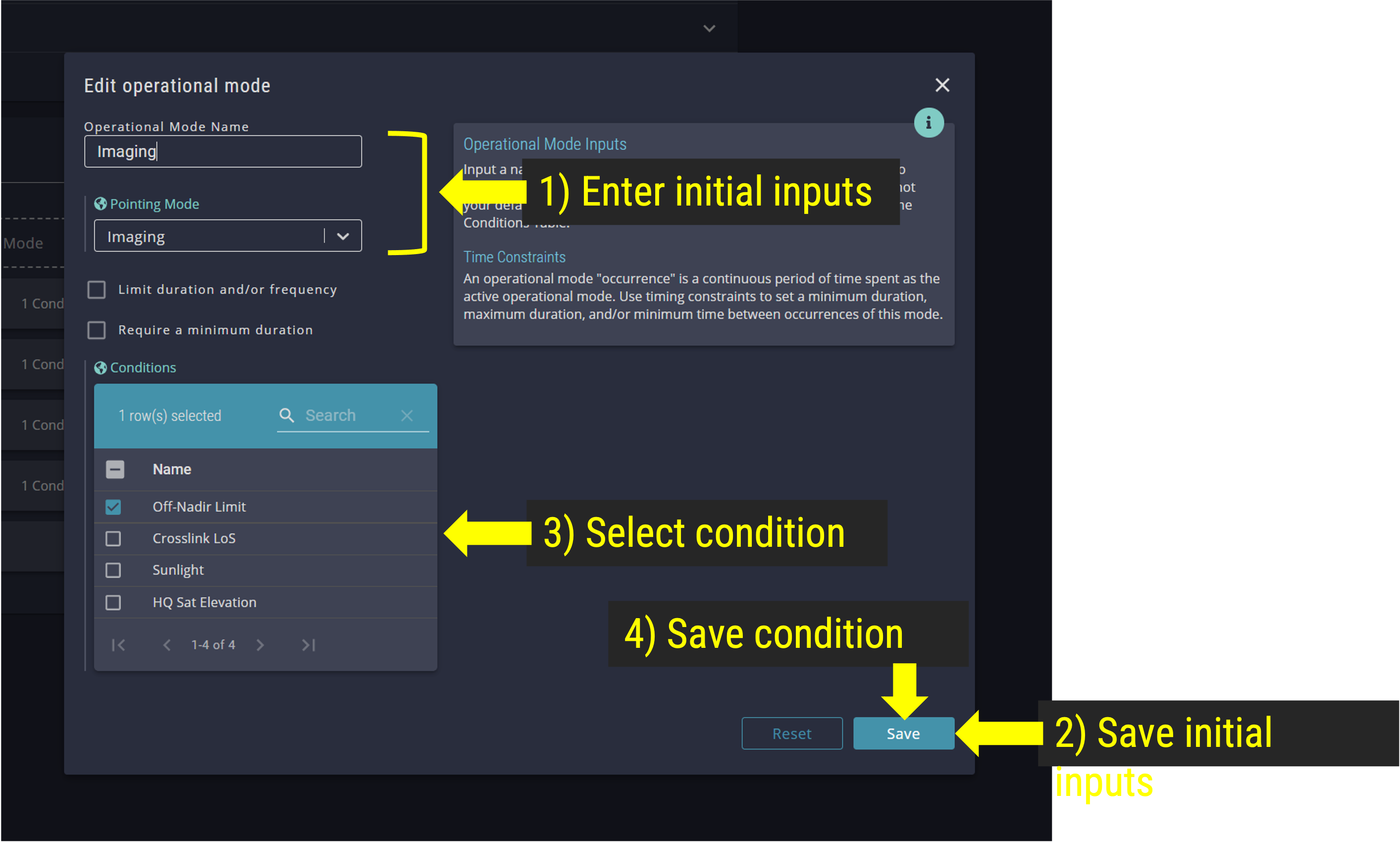
Imaging Op Mode
Step 8.3: Add Crosslink Operational Mode
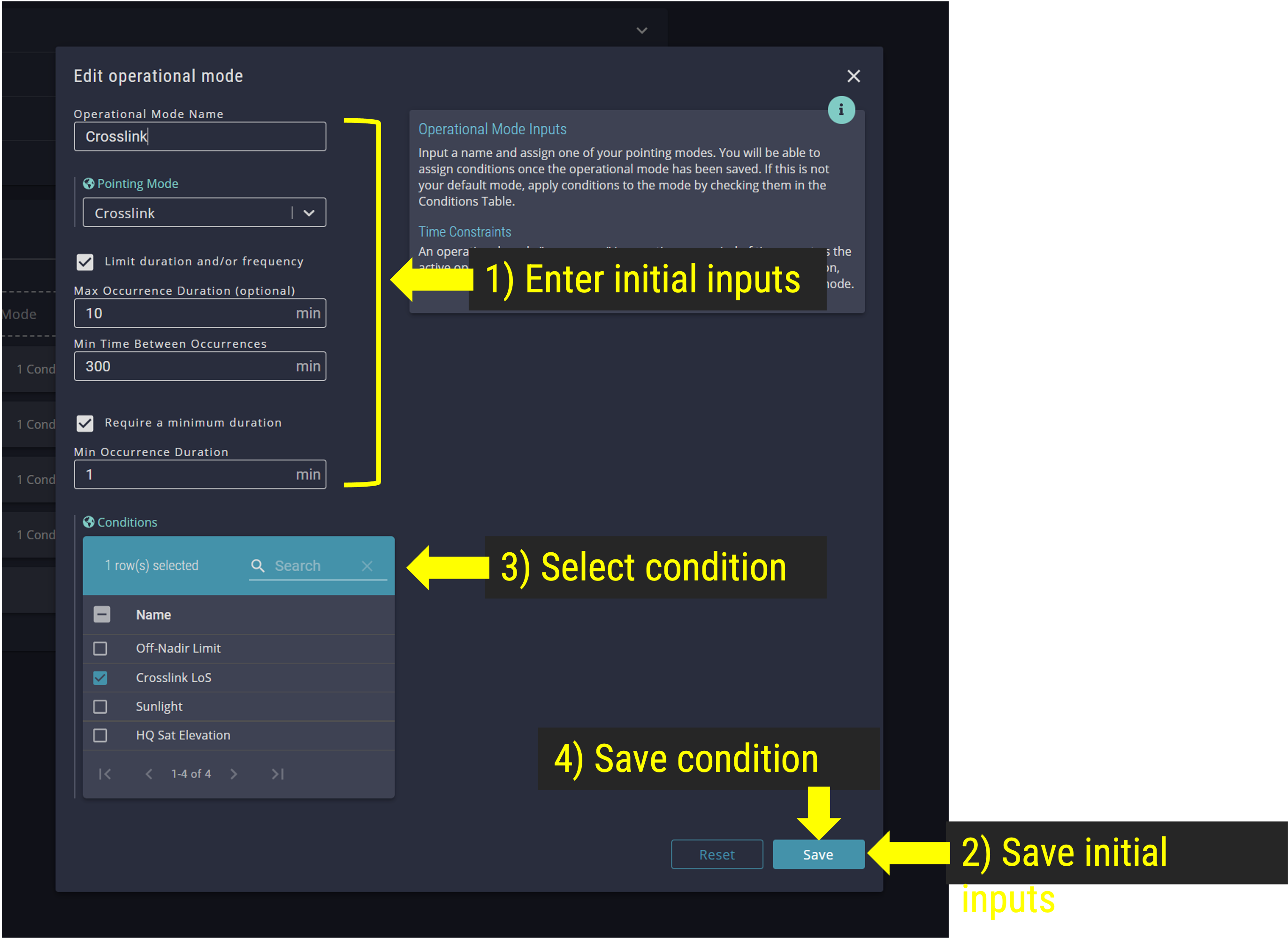
Crosslink Op Mode
Step 8.4: Add Idle Sunlight Operational Mode
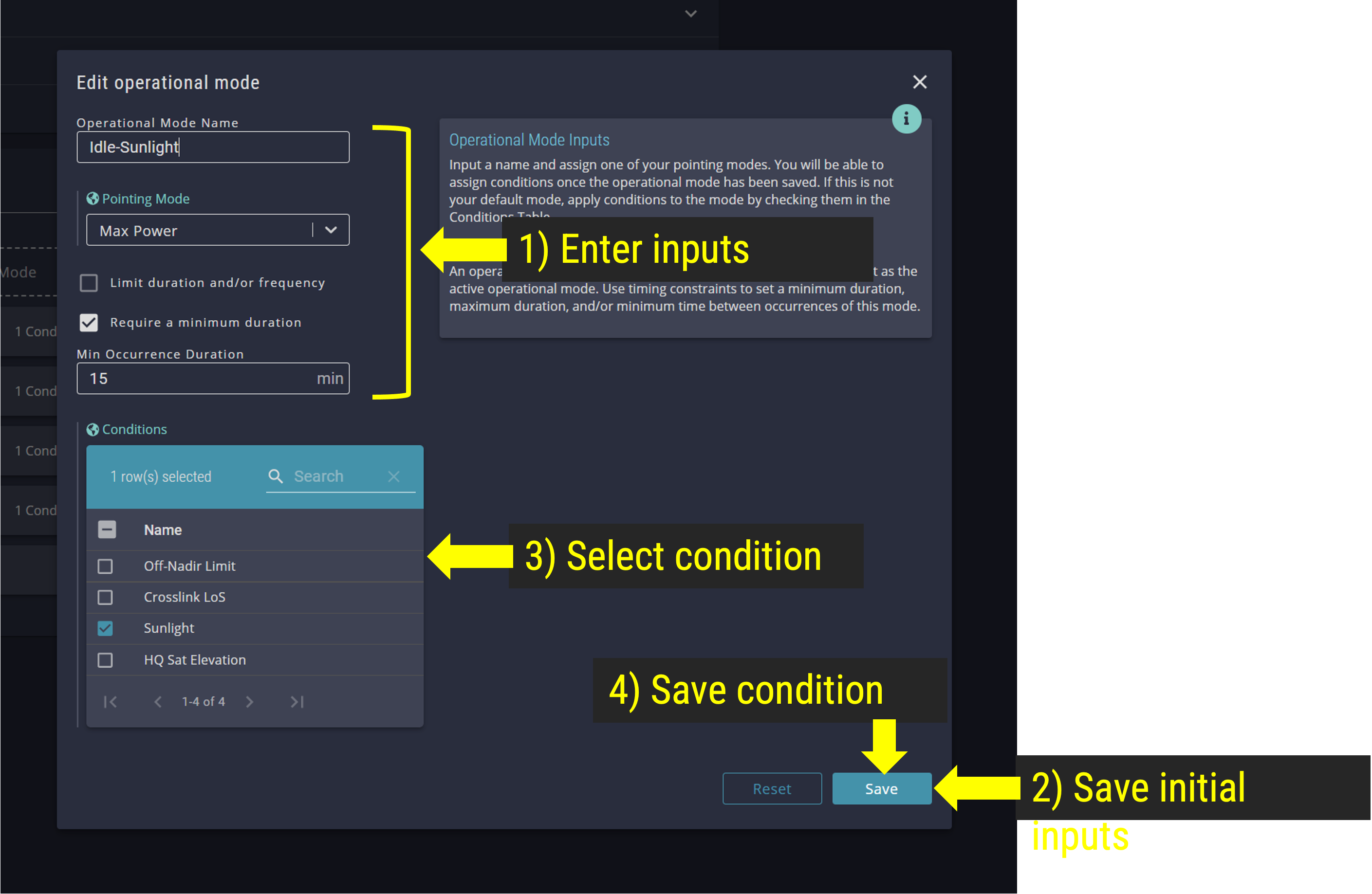
Idle Sunlight Op Mode
Step 8.5: Add Idle Eclipse Operational Mode
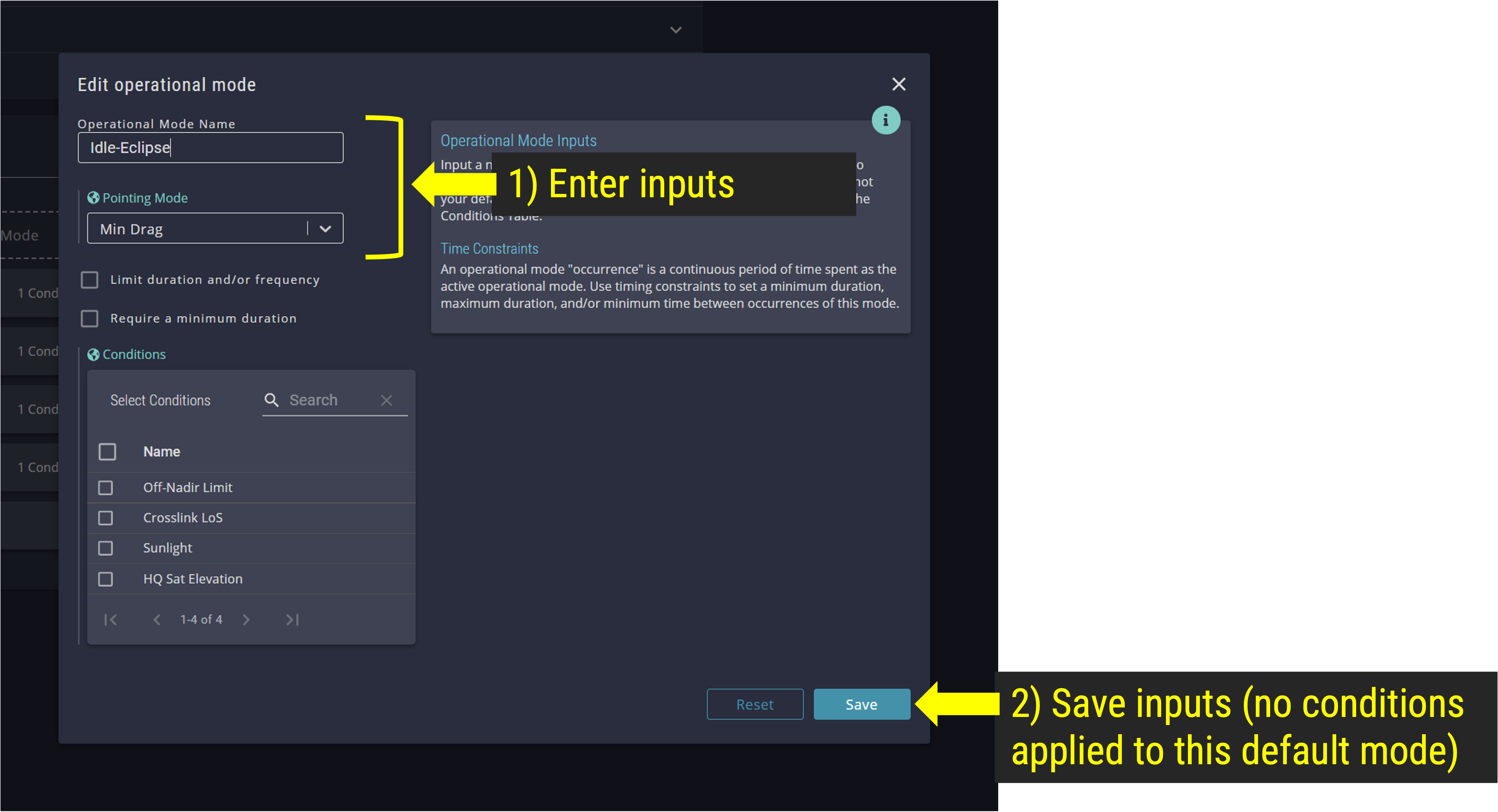
Idle Eclipse Op Mode
Step 8.6: Review Operational Mode Priorities. Click and drag Op Modes to match the priority list shown below.
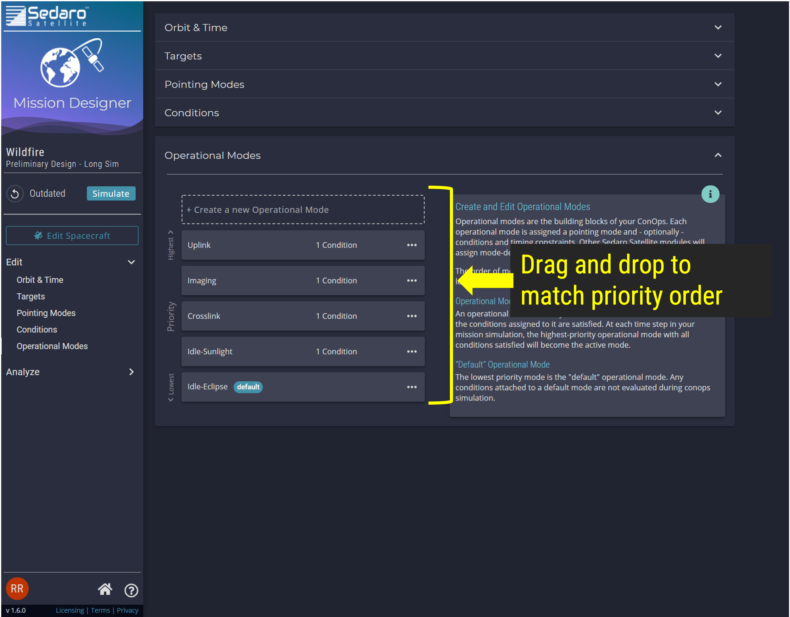
Set Op Mode Priority
Step 9: Simulate your mission by selecting the "Simulate" button in the navigation panel.
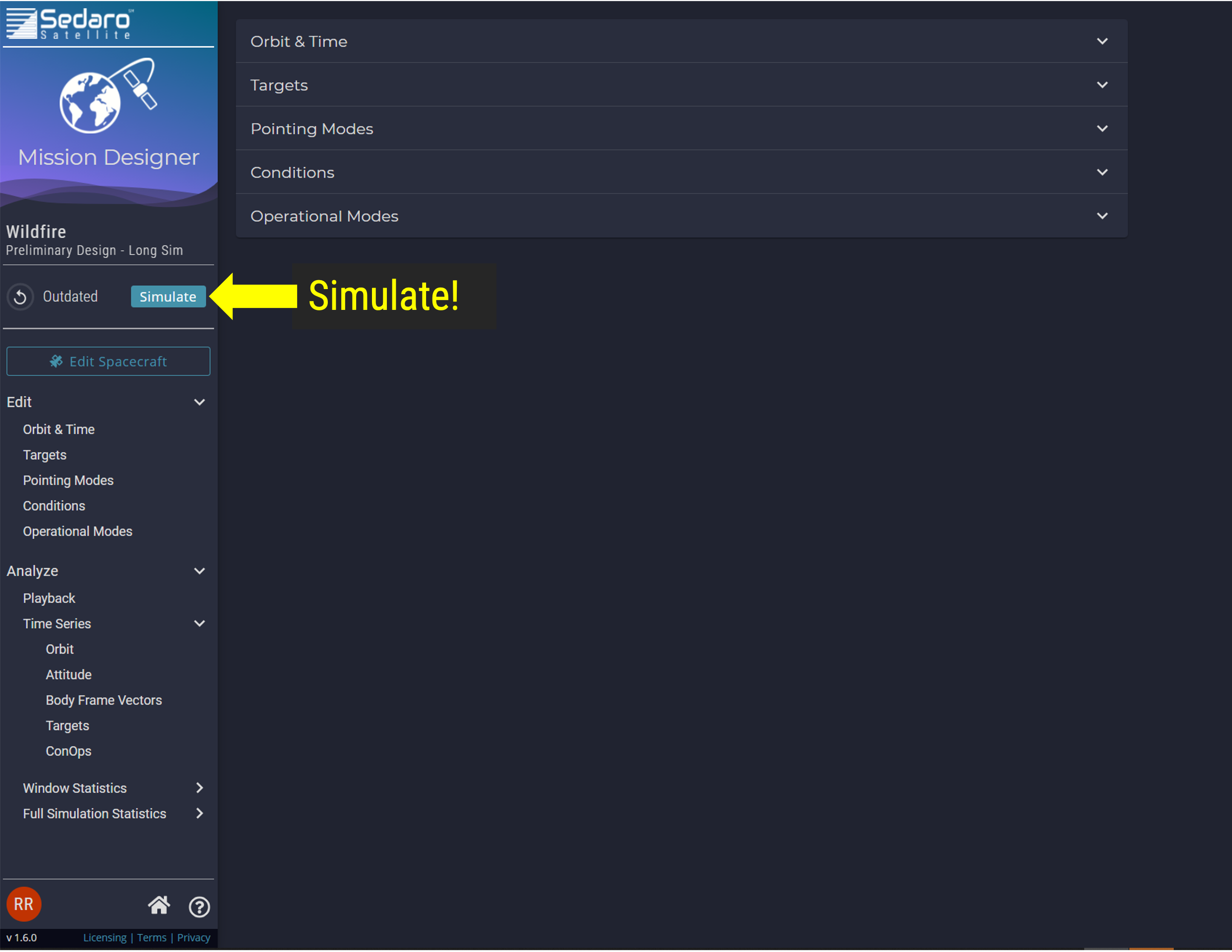
Simulate Mission
Step 10: Select the Analyze boards in the navigation panel to view the simulation results and 3D Playback View.