Power
The Power subsystem is responsible for generating, storing, and distributing power for the spacecraft's components.
Enable Module
To run the Power subsystem on your agent in a scenario, you must enable the Power module by clicking the module toggle.
Enable the power module
Power Processing
Power Controller
The power controller is responsible for processing the power taken in by the satellite and properly distributing it to the satellite's bus regulators and components. There are different kinds�or topologies�of power controllers that behave in various ways. You can use the guidance in the power controller dialog to learn about the different types of supported power controllers in Sedaro. For Wildfire, we will use the Single Converter MPPT topology.
Configure the power controller
Configure the power controller to use the following values:
| Name | Power Processor |
|---|---|
| Topology Type | Single Converter Maximum Peak Power Point Tracking |
| Output Power Rating | 2000 W |
| BCR Efficiency | 85% |
Remember to save the configuration using the Save button so that your changes take effect.
Bus Regulators
Bus regulators are used to take power output from the power controller and regulate it to different voltages for components that require it. For example, if our power controller had a bus voltage of 28 V (or did not have a regulated voltage at all) and one of our components required a 12 V input voltage, we would need to use a bus regulator to provide a power source with the proper voltage to the component.
Create a bus regulator
Create the following bus regulators:
| Bus Regulator Name | Input Source | Voltage | Efficiency | Output Power Rating |
|---|---|---|---|---|
| 28 V | EPS Root Node Output | 28 V | 83% | 1500 W |
| 12 V | Bus Regulator Output: 28 V | 12 V | 82% | 1000 W |
Power Generation
Solar Cells
Solar cells are the building blocks of solar panels, which consist of multiple solar cells stranded together in series and then again in parallel. You must first define a solar cell before you can reference it when creating a solar panel.
Define a solar cell
Define the following solar cell:
| Part Number | XTE-SF |
|---|---|
| Manufacturer | Spectrolab |
| Open Circuit Voltage | 2.75 V |
| Short Circuit Current | 0.5022 A |
| Max Power Voltage | 2.435 V |
| Max Power Current | 0.4833 A |
| Number of Junctions | 3 |
Solar Panels
Solar Panels consist of multiple solar cells connected in series and then in parallel. You must specify which solar cell each panel uses and on which surfaces the panels are installed.
Create a solar panel
Add the following solar panels:
| Name | Installed Surface | Solar Cell | Number of Cells in Series | Number of Cells in Parallel | Add Blocking Diode |
|---|---|---|---|---|---|
| +Y Fixed Solar Panel | Solar Panel +Y Fixed Surface | XTE-SF | 12 | 6 | |
| -Y Fixed Solar Panel | Solar Panel -Y Fixed Surface | XTE-SF | 12 | 6 | |
| +Y Sun Track Solar Panel | Solar Panel +Y Sun Track Surface | XTE-SF | 12 | 16 | |
| -Y Sun Track Solar Panel | Solar Panel -Y Sun Track Surface | XTE-SF | 12 | 16 |
Solar Arrays
Solar arrays are used to group sets of solar panels together.
Create a solar array
Add the following solar arrays:
| Solar Array Name | Solar Panels |
|---|---|
| Fixed Panels | +Y Fixed Solar Panel, -Y Fixed Solar Panel |
| Sun Tracking Panels | +Y Sun Track Solar Panel, -Y Sun Track Solar Panel |
Energy Storage
Battery Cells
Battery cells are the building blocks of battery packs, which consist of multiple battery cells in specific configurations.
Create a battery cell
Add a battery cell with the following parameters:
| Part Number | LP33330 |
|---|---|
| Manufacturer | EaglePicher Technologies |
| Capacity | 6 Ah |
| Equivalent Series Resistance | 0.0146 Ω |
| Maximum Charge Current | 3 A |
| Maximum Discharge Current | 24 A |
| Minimum State of Charge | 0% |
SoC vs Voc Curve
To properly model the behavior of battery cells, we must specify multiple points on the cell's state of charge and open-circuit voltage curve. This curve defines the open-circuit voltage behavior as the state of charge changes.
Define the battery cell's SoC curve
Add the following points to the battery cell's SoC vs Voc curve and save the battery cell:
| SoC (%) | 0 | 10 | 20 | 30 | 40 | 50 | 60 | 70 | 80 | 90 | 100 |
|---|---|---|---|---|---|---|---|---|---|---|---|
Voc (V) | 3 | 3.4 | 3.45 | 3.5 | 3.55 | 3.6 | 3.7 | 3.75 | 3.85 | 3.95 | 4.1 |
Battery Packs
Battery packs combine individual battery cells by connecting the cells together in series, which compounds the voltage of the strand with each cell added. These strands of cells connected in series can then be further connected in parallel with other stands, increasing the capacity of the battery as a whole with each strand added in parallel.
Create a battery pack
Add a battery with the following configuration using the battery cell we defined above:
| Name | Battery Cell | Cells in Parallel | Cells in Series |
|---|---|---|---|
| Battery Pack A | LP33330 | 2 | 8 |
| Battery Pack B | LP33330 | 2 | 8 |
Battery System
The battery system adds another level of combining the satellite's battery packs in series or in parallel. This is useful when the spacecraft's batteries are located in different parts around the spacecraft and/or use different battery cells.
Define the battery system
Set the pack configuration to Parallel and the Initial State of Charge to 80%. You do not need to override any cell values that you previously set; you can leave those optional inputs blank.
Subsystem Loading
Here you establish which power loads will be active for each component while specific operational modes are active.
Add a load state
The dynamics loading for actuators and temperature controllers is automatically calculated based off of given component attributes and the instantaneous demand during the simulation. However, only the active loading for these types of components is automatically calculated. Here you will still need to include any quiescent (passive) power loads for those components.
To add power loadings to the Thermal subsystem's components, you will have to first complete the Temperature Controllers section. You can use the checkboxes in the table below to keep track of which loadings you have added. Add the following component loads:
| Subsystem | Component | Load State Name | Load State Efficiency | Load Name | Source Type | Duty Cycled | Load Type | Power (W) | Operational Modes | | :---------------: | :--------------: | :-------------: | :-------------------: | :-------: | :------------------------: | :--------------------------------: | :------------: | :-------: | :-------------------------: | ------------------------- | | Power | Power Processor | Nominal | 0% | Quiescent | Power Controller Bus | | Constant Power | 12 | All | | | Power | Battery Pack A | Protection | 0% | Quiescent | Power Controller Bus | | Constant Power | 4 | All | | | Power | Battery Pack B | Protection | 0% | Quiescent | Power Controller Bus | | Constant Power | 4 | All | | | Command & Control | Flight Computer | Nominal | 0% | Active | Bus Regulator Output: 12 V | | Constant Power | 50 | All | | | Data Handling | Crosslink Modem | Nominal | 0% | Active | Bus Regulator Output: 28 V | | Constant Power | 120 | Crosslink | | | Data Handling | Crosslink Modem | Standby | 0% | Idle | Bus Regulator Output: 28 V | | Constant Power | 50 | Imaging, Standby | | | GNC | GPS | Nominal | 0% | Active | Bus Regulator Output: 28 V | | Constant Power | 3 | All | | | GNC | Star Tracker | Nominal | 0% | Active | Bus Regulator Output: 28 V | | Constant Power | 4 | All | | | GNC | Magnetometer | Nominal | 0% | Active | Bus Regulator Output: 28 V | | Constant Power | 2 | All | | | GNC | Gyro | Nominal | 0% | Active | Bus Regulator Output: 12 V | | Constant Power | 3 | All | | | GNC | MT-X | Nominal | 0% | Idle | Bus Regulator Output: 12 V | | Constant Power | 0.15 | All | | | GNC | MT-Y | Nominal | 0% | Idle | Bus Regulator Output: 12 V | | Constant Power | 0.15 | All | | | GNC | MT-Z | Nominal | 0% | Idle | Bus Regulator Output: 12 V | | Constant Power | 0.15 | All | | | GNC | RW-X | Nominal | 0% | Idle | Bus Regulator Output: 28 V | | Constant Power | 3 | All | | | GNC | RW-Y | Nominal | 0% | Idle | Bus Regulator Output: 28 V | | Constant Power | 3 | All | | | GNC | RW-Z | Nominal | 0% | Idle | Bus Regulator Output: 28 V | | Constant Power | 3 | All | | | GNC | Thruster | Nominal | 0% | Firing | Bus Regulator Output: 28 V | | Constant Power | 35 | Burning | | | GNC | Thruster | Nominal | 0% | Heaters | Bus Regulator Output: 28 V | | Constant Power | 15 | Burning | | | GNC | Thruster | Standby | 0% | Heaters | Bus Regulator Output: 28 V | | Constant Power | 15 | Orbit Raising | | | Thermal | Payload Cooler | Nominal | 0% | Idle | Bus Regulator Output: 12 V | | Constant Power | 0.1 | Imaging, Crosslink, Standby | | | Payload | Payload Computer | Nominal | 0% | Active | Bus Regulator Output: 12 V | | Constant Power | 250 | Imaging | | | Payload | Payload Computer | Standby | 0% | Idle | Bus Regulator Output: 12 V | | Constant Power | 30 | Crosslink, Standby | | | Payload | Payload Camera | Nominal | 0% | Active | Power Controller Bus | | Constant Power | 40 | Imaging | | | Payload | Payload Camera | Standby | 0% | Idle | Power Controller Bus | | Constant Power | 3 | Crosslink, Standby | |
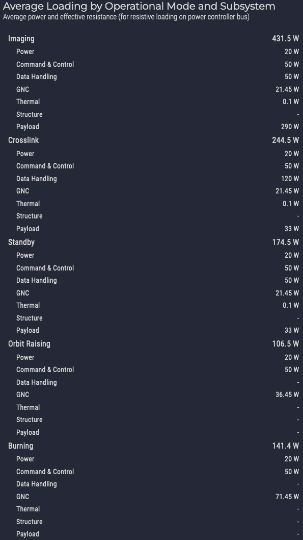
At the bottom of the Subsystem Loading page you can see the Average Loading by Operational Mode and Subsystem table. When you have added all of the component loads, your table should look like the following: