Power Processing
Power is processed on the spacecraft by a Power Processor and optionally regulated by one or more Bus Regulators.
Power Processor
The power controller manages the generation and distribution of power throughout the satellite's Electric Power System (EPS), and is characterized by its topology. Sedaro currently supports five topologies, listed below. The processor is modeled as a single component, so in addition to specifying the ratings particular to the topology, the user must also provide the thermal properties of the processor.
Single-Converter Maximum Peak Power Tracking
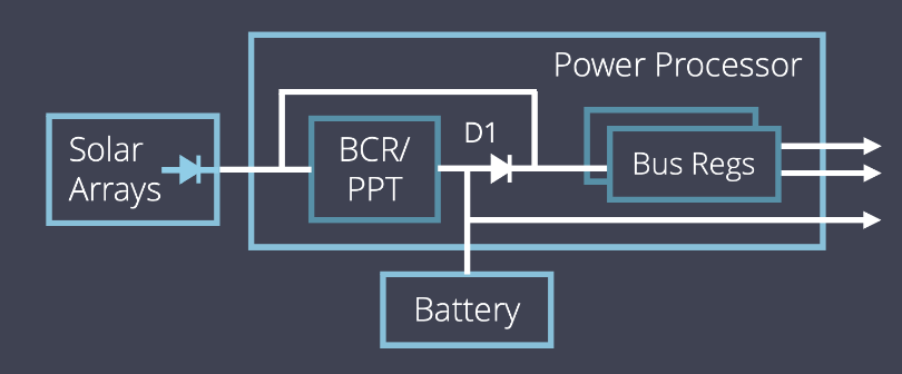
Uses a single BCR/PPT converter per array to regulate battery charging and track the maximum power point of the array. A spacecraft's arrays and battery can provide power simultaneously. Battery discharge is not regulated.
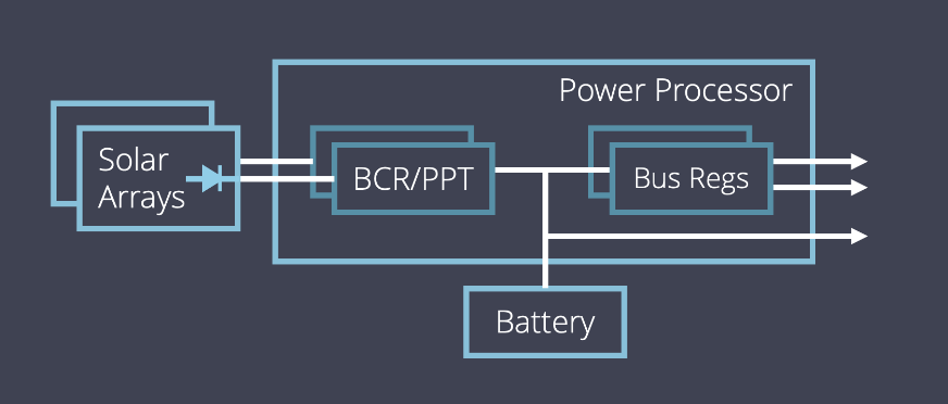
Single-Converter MPPT Diagram
Two-Converter Maximum Peak Power Point Tracking
Uses a PPT to track the maximum power point of the solar arrays, and a BCR to regulate battery charging. A spacecraft's arrays and battery cannot provide power simultaneously. Battery discharge is not regulated.
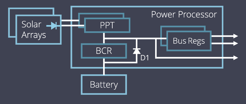
Two-Converter MPPT Diagram
Quasi-Regulated Direct Energy Transfer
Uses a shunt regulator to regulate controller bus voltage and shunt excess solar power. A spacecraft's array and battery cannot provide power simultaneously. Battery discharge is not regulated.
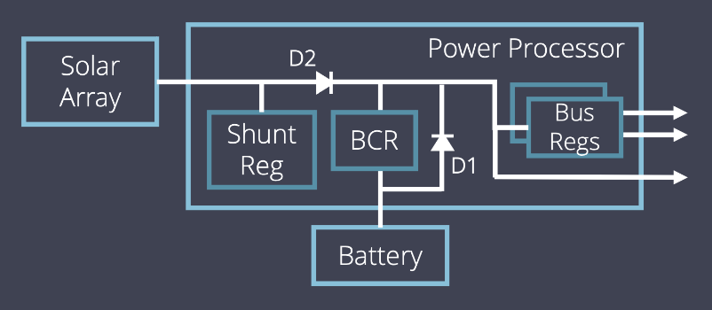
Quasi-Regulated DET Diagram
Fully-Regulated Direct Energy Transfer
Uses a shunt regulator to regulate controller bus voltage and shunt excess solar power. A spacecraft's array and battery cannot provide power simultaneously. Battery discharge is regulated to maintain a constant controller bus voltage.
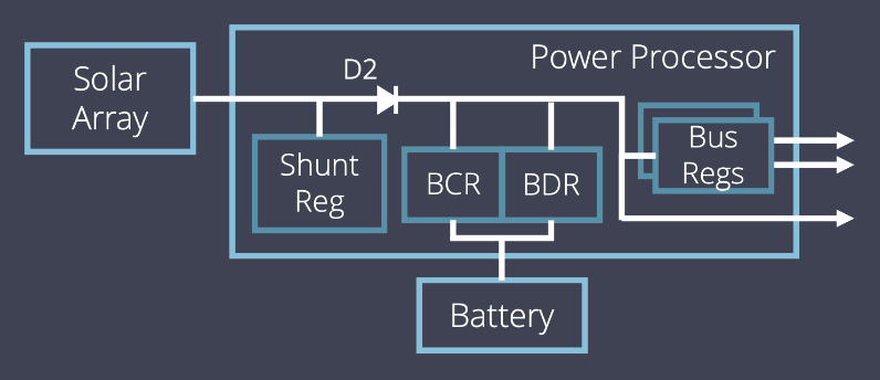
Fully-Regulated DET Diagram
Single-Converter Hybrid
Uses a single BCR/PPT converter to regulate battery charging and track the maximum power point of the array. A spacecraft's array and battery cannot provide power simultaneously to the bus regulators but can both provide power to the unregulated controller bus. Battery discharge is not regulated.
Single-Converter Hybrid Diagram
Bus Regulators
Bus Regulators regulate their output to a fixed voltage for the components and bus regulators that they provide power to. Bus Regulators are characterized by their operating voltage, efficiency, and power rating and may themselves be powered either by the power processor or by another bus regulator. Note the path of power generation must lead back to the power processor in order to simulate.